Cutting head folding device of concrete cutting machine

A technology of folding device and cutting head, which is applied in the direction of roads, stone processing tools, working accessories, etc., can solve the problem of inconvenient transportation of cutting machines, and achieve the effect of ensuring stability and large folding space

Inactive Publication Date: 2015-03-11
重庆健杰科技有限公司
View PDF0 Cites 0 Cited by
  • Summary
  • Abstract
  • Description
  • Claims
  • Application Information

AI Technical Summary

Problems solved by technology

When the work is finished, the cutting piece protruding downward will cause a certain degree of inconvenience to the handling of the cutting machine

Method used


Image

  • Cutting head folding device of concrete cutting machine

Examples


Embodiment Construction

[0013] The present invention will be described in further detail below by means of specific embodiments:

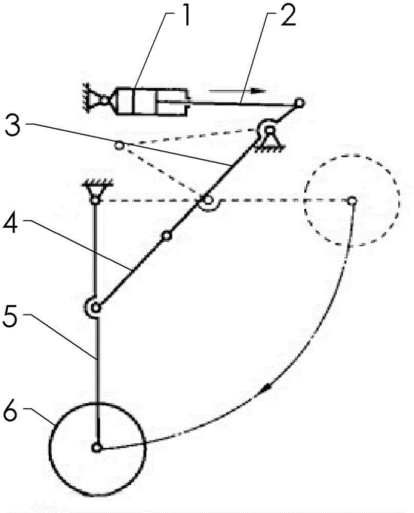
[0014] The reference signs in the drawings of the description include: telescopic cylinder 1 , piston rod 2 , first connecting rod 3 , second connecting rod 4 , swing rod 5 , and cutting head 6 .

[0015] The embodiment is basically as attached figure 1 Shown: the rear end of the left part of the telescopic cylinder is hinged on the frame, and its initial position is generally horizontal. The telescopic cylinder can rotate around the frame at its rear end as a fulcrum, and the exposed part of the piston rod is provided with a dust cover (not shown in the figure).

[0016] The bottom of the frame is also hinged with a fork, which can swing within the fourth interval in the figure, and the free end below the fork is connected to the cutting head.

[0017] The right end of the piston rod is hinged to the driving end of the first connecting rod, the middle section of the fi...


PUM


Abstract

The invention discloses a cutting head folding device of a concrete cutting machine capable of folding the cutting head of the cutting machine during the transporting time. The cutting head folding device of the concrete cutting machine comprises a rack, which is jointed and mounted with a flexible air cylinder, the flexible air cylinder can rotate around the rack by taking the rear end as the pivot, an oscillating bar is jointed below the rack, the free end of the oscillating bar is provided with the cutting head, the piston rod of the flexible air cylinder is jointed to the middle section of the oscillating bar through a first connection rod and a second connection rod, the middle section of the first connection rod is jointed to the rack, the drive end of the first connection rod is jointed to the free end of the piston rod, the driven end of the first connection rod is jointed to the drive end of the second connection rod, the driven end of the second connection rod is jointed to the middle section of the oscillating bar. While folding the cutting head, the piston rod of the flexible air cylinder extends outward for a section of travel, the first connection rod and the second connection rod fold for certain angle for lifting the oscillating bar upward, thereby the cutting head on the oscillating bar can be folded in the rack, the use flexibility of the whole device is guaranteed.

Description

technical field [0001] The invention relates to a concrete cutting machine. Background technique [0002] "Concrete cutting" refers to the construction technology of cutting concrete components, walls, roads, etc. by using tools such as hydraulic wall saws, electric disc saws, water drills or road cutters. It has strong cutting ability, no static damage, and high efficiency. High, water cooling, no construction dust and other characteristics. [0003] The joints cut into concrete pavements are called 'condensation joints'. During the setting and hardening process of concrete, the hydration of cement releases a large amount of heat, which causes the temperature of concrete to rise; most of the hydration reaction of cement ends, and the temperature of concrete begins to drop. During the cooling process, the concrete has solidified and hardened, and the shrinkage caused by the cooling will cause the concrete to crack, and the direction of the cracks is relatively random, whic...

Claims


Application Information

Patent Timeline
Patent Type & Authority Applications(China)
IPC IPC(8): B28D1/24B28D7/00B28D7/02
CPCE01C23/025
Inventor 黄建国
Owner 重庆健杰科技有限公司
Why Eureka
Try Eureka