Injection mould core for refrigerator fan frame

An injection mold and fan technology, which is applied to the field of injection mold cores for the outer frame of refrigerator fans, can solve the problems of difficult fusion and easy fracture of weld lines, and achieve the effects of improving quality, improving service life and reducing development costs.

Inactive Publication Date: 2015-03-11
CHUZHOU JINGHUA MOLD MFG
2 Cites 0 Cited by

AI-Extracted Technical Summary

Problems solved by technology

[0004] Refrigerator cooling fans are generally placed in the refrigerator or in the compressor room, so the structural performance requirements are very strict. The fan frame of the commonly used refrigerator cooling fan is an injection molded part. During the production process, the injection molding machine or/and auxiliary machines do not When it is stable, the injection pressure/holding press...

Abstract

The invention discloses an injection mould core for a refrigerator fan frame, and belongs to the field of injection moulds. The injection mould core comprises three needle point pouring gates, namely a needle point pouring gate 1, a needle point pouring gate 2 and a needle point pouring gate 3, wherein the needle point pouring gates have two diameter sizes; the needle point pouring gate 1 has a relatively large diameter size and is independently positioned on one side of the mould core; the diameter sizes of the needle point pouring gate 2 and the needle point pouring gate 3 are the same and are smaller than that of the needle point pouring gate 1; the needle point pouring gate 2 and the needle point pouring gate 3 are distributed on the other side of the mould core. The injection mould core has the advantages as follows: according to CAE (computer aided engineering) simulation, the three needle point pouring gates with different diameter sizes are optimally designed, and according to the maximum flow length/wall thickness, a specific pouring position is determined so as to transfer a welding mark during injection moulding production of the refrigerator fan frame from an original weak position to a relatively strong end surface, so that the development cost of the mould is greatly reduced, the product quality is improved and thus the service life of a refrigerator cooling fan is prolonged.

Technology Topic

Computer-aided engineeringRefrigerated temperature +2

Image

  • Injection mould core for refrigerator fan frame

Examples

  • Experimental program(1)

Example Embodiment

[0016] In order to make the technical means, innovative features, goals and effects achieved by the present invention easy to understand, the present invention will be further described below in conjunction with specific illustrations.
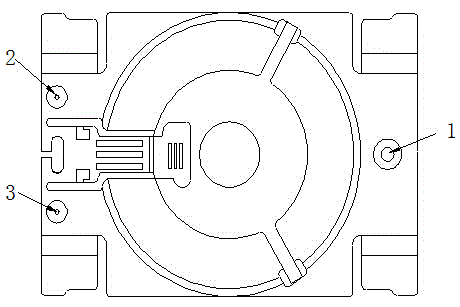
[0017] like figure 1 As shown, a refrigerator fan outer frame injection mold core, the refrigerator fan outer frame injection mold core contains three pin gates, respectively No. 1 pin gate 1, No. 2 pin gate 2 and No. 3 pin gate No. pin gate 3, the pin gate has two sizes of diameters, No. 1 pin gate 1 has a larger diameter and is alone on one side of the mold core, No. 2 pin gate and No. 3 pin gate The same net size, and smaller than the No. 1 pin gate size, distributed on the other side of the core.
[0018] The position of the pinpoint gate of the injection mold core of the refrigerator fan shell is determined as follows: the gate position that can cover the maximum product area within the maximum flow length/wall thickness ratio.
[0019] The diameter of the pin gate is optimized based on CAE simulation, so that the weld line moves from the original weak point to the stronger end face.
[0020] The basic principles, main features and advantages of the present invention have been shown and described above. Those skilled in the industry should understand that the present invention is not limited by the above-mentioned embodiments. What are described in the above-mentioned embodiments and the description only illustrate the principle of the present invention. Without departing from the spirit and scope of the present invention, the present invention will also have Variations and improvements are possible, which fall within the scope of the claimed invention. The protection scope of the present invention is defined by the appended claims and their equivalents.

PUM

no PUM

Description & Claims & Application Information

We can also present the details of the Description, Claims and Application information to help users get a comprehensive understanding of the technical details of the patent, such as background art, summary of invention, brief description of drawings, description of embodiments, and other original content. On the other hand, users can also determine the specific scope of protection of the technology through the list of claims; as well as understand the changes in the life cycle of the technology with the presentation of the patent timeline. Login to view more.

Similar technology patents

AFDX performance test method based on RFC2544

Owner:CHINESE AERONAUTICAL RADIO ELECTRONICS RES INST

Business processing method and apparatus

Owner:BEIJING BAIDU NETCOM SCI & TECH CO LTD

Method of playing network videos online

Owner:GUANGDONG OPPO MOBILE TELECOMM CORP LTD

Classification and recommendation of technical efficacy words

  • Reduce development costs
  • quality improvement

Data processing method and data processing device for recycle bin

InactiveCN101546311AAvoid Code ManipulationReduce development costs
Owner:BEIJING MINGWAN INTERCONNECTION TECH

Rice machining process

InactiveCN103691508Aquality improvementReduce broken rice rate
Owner:聂俊
Why Eureka
Try Eureka