Low-emission reverse flow combustor adopting radial swirl injection and fuel oil grading schemes

A backflow combustor and low-emission technology, which is applied in the direction of combustors, continuous combustors, and combustion methods, can solve the problems of insufficient atomization and evaporation of fuel, incomplete combustion, and unfavorable weight loss of the combustor.

Active Publication Date: 2015-03-11
中科航星科技有限公司
View PDF6 Cites 27 Cited by
  • Summary
  • Abstract
  • Description
  • Claims
  • Application Information

AI Technical Summary

Benefits of technology

This new type of combustor has two parts - one part uses different types of fuels for operation: liquid hydrocarbon (LH) directly injected into an engine's cylinders while diesel oil alone acts as both solvent and lubricant during compression ignition cycles; and another part mixes these liquids together before burning them down at high temperatures. By mixing LH/O2 fuel with oxygen from outside sources instead of just adding it separately, there are fewer steps needed compared to traditional methods that require either diluting more crude oil or replacing existing ones altogether.

Problems solved by technology

The technical problem addressed in these inventions relates to improving diesel exhaust systems used in industrial vehicles without generating excessive amounts of particulate matter while maintaining stable operation during extreme environments like cold start. Current methods involve delivering oxygen enrichments through diffusion sources, leading to poor performance and potential overheating of parts within the system. Therefore, there needs to develop effective catalyst materials capable of effectively decompositing noxious gases produced by burning fuels containing sulfur compounds.

Method used


Image

  • Low-emission reverse flow combustor adopting radial swirl injection and fuel oil grading schemes
  • Low-emission reverse flow combustor adopting radial swirl injection and fuel oil grading schemes
  • Low-emission reverse flow combustor adopting radial swirl injection and fuel oil grading schemes

Examples


Embodiment Construction

[0056] In order to make the technical solution and advantages of the present invention more detailed and clear, the present invention will be further described in detail by listing specific embodiments in conjunction with the attached schematic diagrams below.

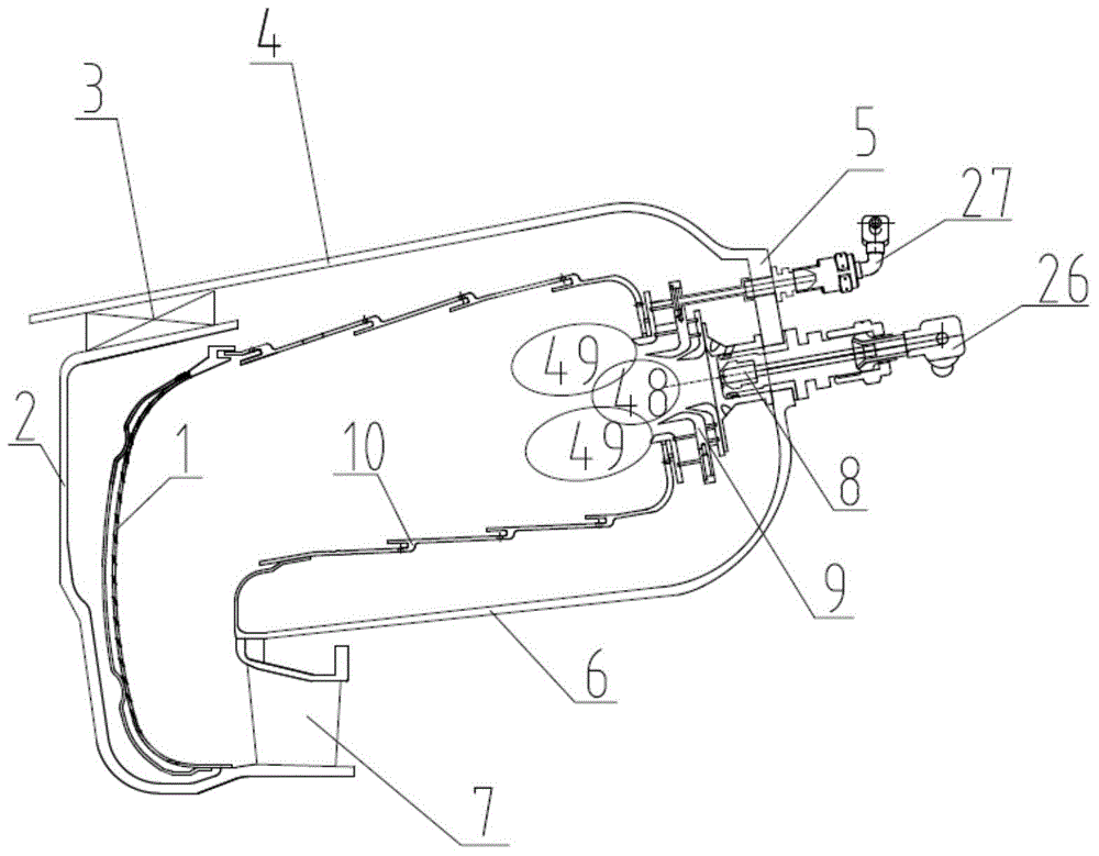
[0057] figure 1 It is a cross-sectional view of a low-emission recirculation combustor proposed by the present invention using a radial swirl intake fuel classification scheme. The low-emission recirculation combustor includes an outer casing 4, a head casing 5, a casing 6 inside the combustion chamber, and a combustion chamber. The gas elbow 1, the nozzle device and the flame tube are characterized in that the nozzle device is arranged on the head of the flame tube, including a duty-level nozzle assembly and a main combustion-level nozzle assembly, and the combustion area at the head of the flame tube is divided into mutually coupled combustion. The duty area in the center and the main combustion area near the outside...


PUM


Abstract

The invention discloses a low-emission reverse flow combustor adopting the radial swirl injection and fuel oil grading schemes. The low-emission reverse flow combustor adopting the radial swirl injection and fuel oil grading schemes is that air flows from a head part of a radial grading three-grade swirler into a flame tube, and while fuel oil flows through an on-duty-grade oil channel and a main-combustion-grade oil channel to reach the combustor, so as to form an on-duty area and a main combustion area in the head part of the combustor; diffusive combustion occurs in the on-duty area, and while pre-mixing combustion is caused in the main combustion area; and a high-temperature product produced by the combustion flows to the downstream, turns in 180 degrees at an exhaust elbow and then is discharged from the combustor. The low-emission reverse flow combustor has the advantages that a central on-duty-grade part works when the combustor is under ignition, starting, slow running and other low load states, thus the combustion efficiency is improved, and the emission of un-combusted materials CO and UHC is decreased; in case of relatively large load above slow running load, the main-combustion-grade oil channel and the on-duty-grade oil channel work together, the on-duty-stage oil channel provides a stable ignition source to the main-combustion-grade oil channel so as to expand the boundary of the combustor; the main combustion area is designed to perform lean-oil combustion under equivalence ratio of 0.6 to 0.65, and the reaction temperature is far below the adiabatic flame temperature, and thus the produced and emitted nitric oxide (NOX) are decreased; and the multi-grade swirl injection and fuel oil grading schemes are applied to the combustor of an aircraft engine or a ground gas turbine.

Description


Claims


Application Information

Patent Timeline
Owner 中科航星科技有限公司
Why Eureka
Try Eureka