
Fuel strut injector

A technology of injector and support plate, applied in combustion chamber, combustion method, combustion equipment and other directions, can solve the problems of high cost of support plate, harsh thermal environment of support plate, complicated structure of support plate, etc., and avoid serious ablation. Effect

Inactive Publication Date: 2016-12-21
NORTHWESTERN POLYTECHNICAL UNIV
View PDF5 Cites 11 Cited by
  • Summary
  • Abstract
  • Description
  • Claims
  • Application Information

AI Technical Summary

Problems solved by technology

However, the strut injector bears extremely high heat load in the engine, especially the leading edge of the strut, which is easily burned during operation
For the thermal protection of the support plate, the conventional method is to use high-temperature-resistant metal materials and use the material heat sink for passive thermal protection, but the thermal environment of the support plate is extremely harsh, and the temperature at the front edge of the support plate in the scramjet engine can reach about 3000K, exceeding The use limit of most existing metal materials, the support plate using metal heat sink cannot work normally for a long time
[0003] The traditional support plates that use high-temperature-resistant materials for passive thermal protection are expensive, and it is currently difficult to find materials that can withstand high temperatures, high heat flow, and thermal environments in the engine for a long time; patent 200910236121. "structure", using the low-temperature gas ejected from the slit at the front edge of the support plate to form a low-temperature gas film on the surface of the support plate to protect the support plate from heat, but the structure of the support plate is relatively complicated and the processing technology is difficult; in the patent 201310561173.6, a A "thermal protection method for scram engine injection struts by sweating and impingement cooling", according to the characteristics of porous media, using fuel as a coolant, combined with the concept of impingement cooling, to achieve the thermal protection effect on injection struts
However, the structure of the support plate is complex, and the porous structure is easy to generate large flow resistance, which has high requirements on the fuel supply system, which is not conducive to fuel injection and mixed combustion

Method used


Image

  • Fuel strut injector
  • Fuel strut injector
  • Fuel strut injector

Examples


Embodiment Construction

[0023] This embodiment is a fuel branch injector.

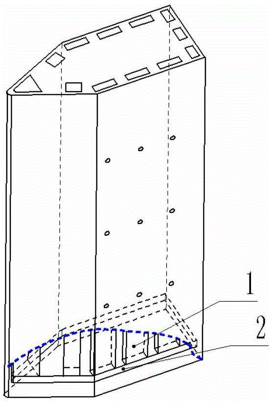
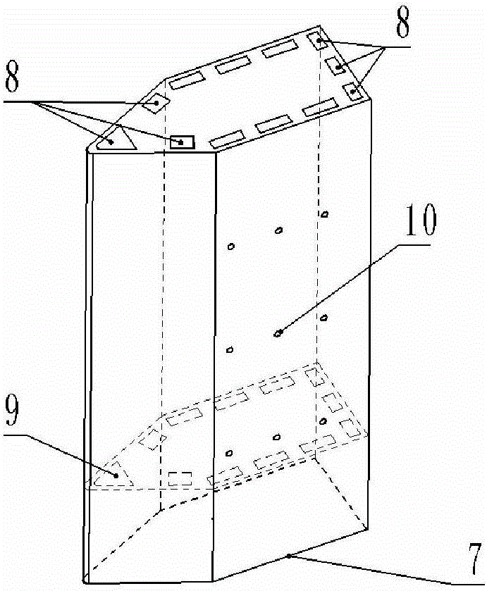
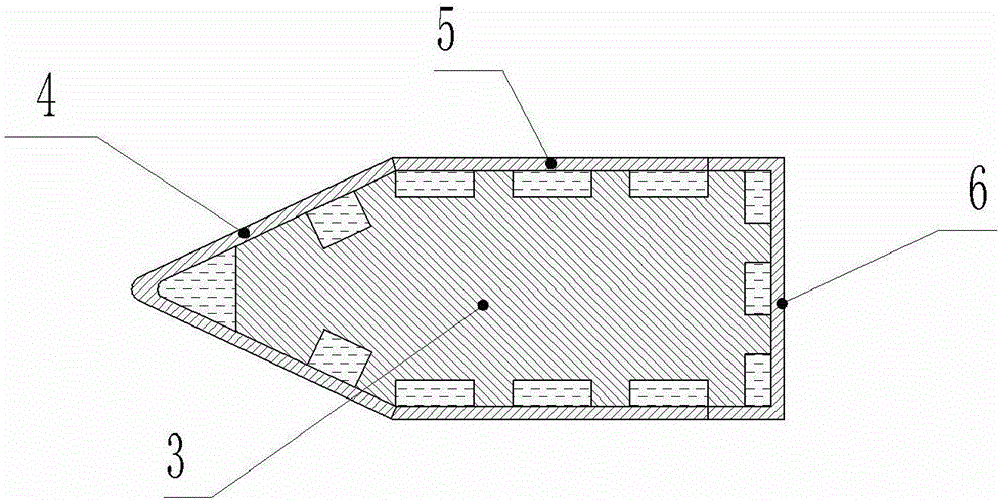
[0024] refer to Figure 1 to Figure 5 , the fuel strut injector in this embodiment uses the fuel of scramjet and combined cycle power engine as coolant, and adopts regenerative cooling mode; the coolant flows in the cooling passage to cool the strut plate, and is sprayed into the combustion chamber and The gas is mixed and burned to realize the normal operation of the support plate for a long time.

[0025] The fuel branch injector in this embodiment includes a cooling channel 1, a liquid collection chamber 2, a support plate 3, a front edge wall surface 4 of the support plate, a side wall surface 5 of the support plate, a rear wall surface 6 of the support plate, a bottom portion of the support plate 7, and a passage inlet 8 , the flow channel 9, the fuel injection hole 10, and the cooling channel is arranged on the inner side of the wall surface close to the support plate; wherein, the support plate 3 is a rounded wedge-sh...


PUM


Abstract

The invention discloses a fuel strut injector. Fuel of a scramjet engine and a combined circulatory power engine is adopted as a cooling agent, the cooling agent flows in a cooling channel for cooling a strut and is sprayed into a combustion chamber for being subjected to mixing combustion together with fuel gas, and therefore long-time normal work of the strut can be realized. The front edge of the strut is of a rounding wedge-shaped structure, and a flowing channel is located on the inner side of the front edge of the strut; a plurality of channel inlets are formed in each of the inner side of a front part of the strut and the inner side of a rear wall of the strut, a plurality of fuel spraying holes are formed in each of side wall surfaces of the strut, a liquid collection cavity is formed in the bottom of the strut and communicates with the flowing channel and the cooling channel, and the cooling agent enters the channel inlets, flows to the bottom of the strut along the channel, is gathered in the liquid collection cavity and finally is sprayed out of the strut through the fuel spraying holes; and the cooling agent absorbs heat in the channel in a flowing heat exchange mode of forced convection before being sprayed into the combustion chamber, and therefore the temperature of the strut can be lowered, and the fuel can be preheated. The strut injector is simple in structure, the thermal protection effect on the strut is good, and the strut can realize the function of injecting the fuel.

Description

technical field [0001] The invention relates to the fields of scramjet engines and combined cycle power engines, in particular to a fuel branch injector with a cooling structure. Background technique [0002] Engine combustion efficiency is closely related to the mixing effect of fuel and air; in order to increase the injection depth of fuel in the high-speed incoming flow, the injected fuel can be more evenly distributed in the mainstream gas of the combustion chamber, and the Mixing efficiency of air, usually using fuel rail injectors. However, the strut plate injector bears extremely high heat load in the engine, especially the front edge of the strut plate, which is very easy to be burned during operation. For the thermal protection of the support plate, the conventional method is to use high-temperature-resistant metal materials and use the material heat sink for passive thermal protection, but the thermal environment of the support plate is extremely harsh, and the te...

Claims


Application Information

Patent Timeline
Patent Type & Authority Applications(China)
IPC IPC(8): F23R3/28
CPCF23R3/283
Inventor 何国强候志远李文强秦飞魏祥庚景婷婷
Owner NORTHWESTERN POLYTECHNICAL UNIV
Learn More