Clustered shunt type thermal protection for turbine rotor blade of aeroengine

A technology for aero-engines and turbine rotors, applied in the direction of engine components, machines/engines, blade support components, etc., can solve the problems of intermittent, uneven distribution of gas film holes, uneven gas film, etc.

Inactive Publication Date: 2009-11-25
张金山
View PDF0 Cites 8 Cited by
  • Summary
  • Abstract
  • Description
  • Claims
  • Application Information

AI Technical Summary

Problems solved by technology

Air film cooling is an effective thermal protection measure. The surface air film is formed by the cooling gas in the inner cavity of the blade flowing out from a large number of air film holes on the wall of the blade. Although it can prevent the gas from corroding the solid wall material of the hot end parts , but since the air film hole is directly opened from the blade wall to the inner cavity of the blade, if there are too many air film holes, it will inevitably affect the strength of the blade
Moreover, the distribution of air film holes is intermittent and uneven, the air film produced is also uneven and unstable, the flow path is short, and the utilization rate of cooling air is not high, which will affect the heat insulation effect
In addition, although divergent cooling is more effective, it has not been applied in practice because the divergent test blades are made of porous materials, which are easily blocked by dust in the air-conditioning, and the porous materials are oxidized and corroded, which affects the service life.

Method used


Image

  • Clustered shunt type thermal protection for turbine rotor blade of aeroengine
  • Clustered shunt type thermal protection for turbine rotor blade of aeroengine
  • Clustered shunt type thermal protection for turbine rotor blade of aeroengine

Examples


Embodiment Construction

[0012] Embodiments of the present invention will be further described below in conjunction with the accompanying drawings.

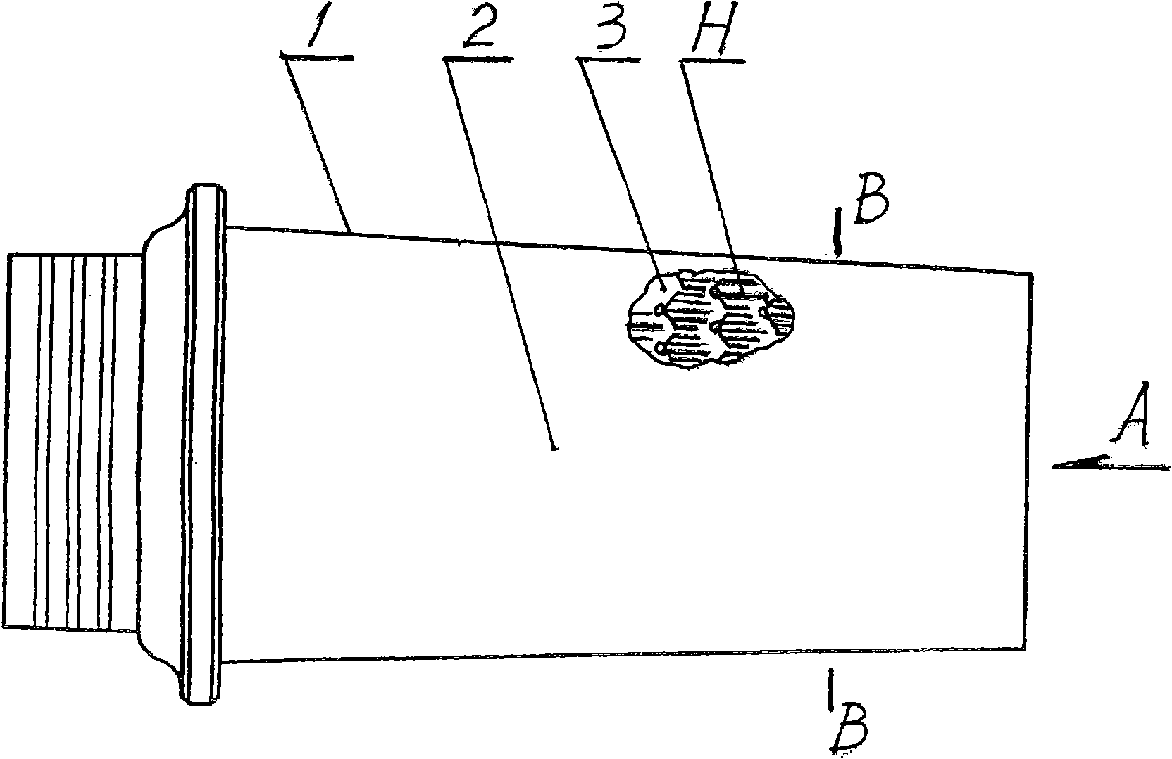
[0013] refer to figure 1 A plurality of cooling units H are arranged on the surface of the load-bearing skeleton 3 below the blade wall 2 of the turbine rotor blade 1 , and are distributed from the center of the turbine to the tail end of the turbine rotor blade 1 . The B-B section of the internal structure is expressed by A.

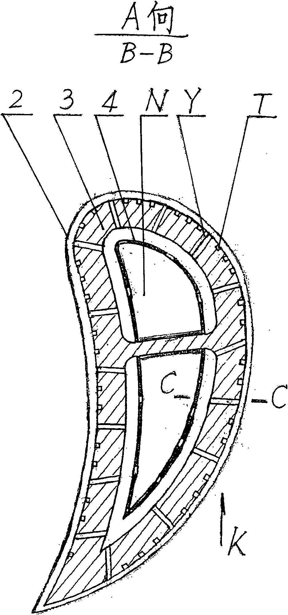
[0014] refer to figure 2 , the outer layer of the turbine rotor blade 1 is the blade wall surface 2, which is fixedly laid on the outside of the load-bearing framework 3, and the inner cavity N of the blade is formed inside, and the inner cavity spacer 4 is arranged in the inner layer. A number of air-introduction holes Y are provided around the load-bearing frame 3 to communicate with the inner cavity N of the blade, and a number of airflow channels T are opened on the outer layer of the load-bearing frame 3 .

[0015] refer ...


PUM


Abstract

The invention discloses clustered shunt type thermal protection for a turbine rotor blade of an aeroengine. A load bearing frame (3) of the turbine rotor blade (1) is provided with a plurality of air bleeding holes (Y) which are communicated with an inner cavity (N) of the blade, each air bleeding hole (Y) is communicated with a plurality of gas channels (T) to form a cooling unit (H), and the load bearing frame (3) is densely distributed with a plurality of the cooling units (H). Cooling air in the inner cavity (N) of the blade flows toward the gas channels (T) through the air bleeding holes (Y), and is sprayed outward through a micro-air film hole (W) and a dust exhaust air film hole (P) on a blade wall surface (2) to form an air film (M), and strengthened heat exchange cooling is performed on a hot end of the turbine rotor blade (1), and separation is performed on heat transfer. The thermal protection can enlarge the area of cooling and heat exchange, prolong cooling time, improve the utilization rate of the cooling air, strengthen thermal protection property, and improve the temperature of fuel gas in front of turbines of the aeroengines.

Description

technical field [0001] The invention relates to an aviation turbofan engine, in particular to a protection technology for improving the high temperature resistance performance of a hot end component. Background technique [0002] In 2006, my country announced the successful development of the J-10 fighter jet and engine, marking the historic leap from the second generation to the third generation of my country's military aircraft. From the perspective of the development trend of aero-engines, increasing the gas temperature before the turbine has become an important technical way to improve the performance of aero-engines. At present, the cooling and thermal protection measures commonly used for aero-engine turbine blades include air film cooling on the outside and convective heat exchange cooling on the inside of the blade cavity. For the turbofan engine installed on the J-10 fighter jet, the temperature of the gas in front of the turbine is about 1500°C. The turbine blade...

Claims


Application Information

Patent Timeline
Patent Type & Authority Applications(China)
IPC IPC(8): F01D5/14
Inventor 张金山
Owner 张金山
Why Eureka
Try Eureka