Adaptive local activation transpiration cooled hypersonic speed leading edge thermal-protection method

A technology of sweating cooling and hypersonic speed, applied in the direction of heat reduction structure, aircraft parts, fuselage, etc., can solve the problem of low cooling efficiency, achieve the effect of improving thermal protection effect and optimizing utilization

Inactive Publication Date: 2018-08-24
UNIV OF SCI & TECH OF CHINA
View PDF6 Cites 7 Cited by
  • Summary
  • Abstract
  • Description
  • Claims
  • Application Information

AI Technical Summary

Problems solved by technology

Although the phase change sweating cooling of liquid coolant presents a better cooling effect, there is still a lot of room for improvement. For example, at the stagnation point at the leading edge of a hypersonic vehicle, the cooling efficiency is often the lowest due to the highest heat flux density and aerodynamic pressure. of

Method used


Image

  • Adaptive local activation transpiration cooled hypersonic speed leading edge thermal-protection method
  • Adaptive local activation transpiration cooled hypersonic speed leading edge thermal-protection method
  • Adaptive local activation transpiration cooled hypersonic speed leading edge thermal-protection method

Examples


specific Embodiment approach

[0017] The preferred specific implementation of the hypersonic leading edge thermal protection method for self-adaptive local activation of sweat cooling of the present invention is:

[0018] include:

[0019] A leading edge body with a microporous structure is prepared by using a high temperature resistant material, and a layer of sublimation impermeable ablation coating is covered on the surface of the leading edge body;

[0020] A coolant supply channel is fixedly connected to the rear of the leading edge body, and the coolant is pre-sealed in the cooling cavity surrounded by the leading edge body;

[0021] When the surface temperature of the ablative coating is below the sublimation temperature of the material of the ablative coating, the pores of the surface are closed and the sweat cooling system is not activated;

[0022] Under the action of external changing heat flow, the ablative coating located at the stagnation point of the leading edge body with high heat flow is...

specific Embodiment

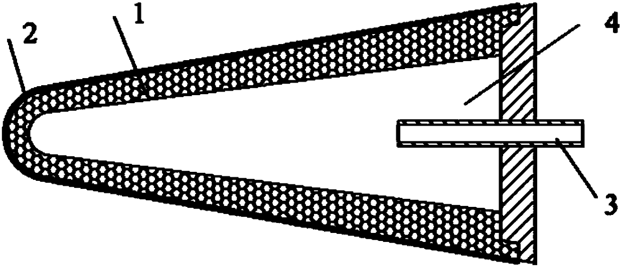
[0036] Such as figure 2 , image 3 As shown, the present invention includes a leading edge body 1 with a microporous structure prepared from a high temperature resistant material. The surface of the porous leading edge is covered with a layer of sublimation-type impermeable ablation coating 2. Behind the leading edge body 1 The part is connected with the coolant supply passage 3, and the coolant is sealed in the cooling cavity 4 in advance. Such as figure 2 As shown, when the surface temperature of the coating 2 is lower than the sublimation temperature of the ablation material, the pores on the surface of the porous front 1 are closed, and the active sweating cooling system is not activated at this time; image 3 As shown, under the action of externally changing heat flow, the ablative coating 2 located in the local high heat flow region of the stagnation point of the leading edge is sublimated preferentially, the active sweating cooling mechanism is locally activated, an...


PUM


Abstract

The invention discloses an adaptive local activation transpiration cooled hypersonic speed leading edge thermal-protection method. A high temperature-resistant material is used for preparing a leadingedge body having a microporous structure, the surface of the leading edge body is covered with a layer of sublimation-type impervious ablation coating, a coolant supply channel is fixedly connected with a rear part of the leading edge body, and a cooling chamber enclosed by the leading edge body is sealed with a coolant in advance; the surface temperature of the ablation coating is lower than thesublimation temperature of the material of the ablation coating, an aperture at the surface is enclosed, and at this time, a transpiration cooled system cannot be activated; under effect of externalchange hot fluid, the ablation coating of a high hot-fluid area positioned at a leading edge body arrest point gives priority to sublimation, an active transpiration cooled mechanism is partially activated, the coolant is leaked from the aperture, a layer of a protection gas film is used for covering, and local thermal protection of the area can be enhanced. The method can increase the thermal-protection effect of a high hot-fluid area of a leading edge arrest point, and the optimized utilization of the coolant amount is realized.

Description

technical field [0001] The invention relates to an aircraft thermal protection technology, in particular to a hypersonic leading edge thermal protection method for adaptive local activation of sweat cooling. Background technique [0002] With the development of hypersonic vehicle technology, the problem of its thermal protection has become increasingly prominent. For some key parts of the hypersonic vehicle, such as the leading edge cap, the leading edge of the wing, and the lip of the air intake, the thermal problem is more severe. Figure 1a with Figure 1b The thermal environment characteristics of a single leading edge are given, and it can be seen that compared with the blunt leading edge of the space shuttle, the peak heat flow of the sharp leading edge is higher, especially in the stagnation point region of the leading edge. Therefore, designing and developing an efficient active thermal protection system is the key to solving the problem of thermal protection. [0...

Claims


Application Information

Patent Timeline
Patent Type & Authority Applications(China)
IPC IPC(8): B64C1/38B64C3/36
CPCB64C1/38B64C3/36
Inventor 王建华伍楠贺菲丁锐
Owner UNIV OF SCI & TECH OF CHINA
Why Eureka
Try Eureka