
Laser positioning device

A technology of laser positioning and laser instrument, applied in the field of automobile crash test, can solve the problem of inaccurate positioning error of laser instrument, and achieve the effect of improving work efficiency, small error and high measurement accuracy

Active Publication Date: 2015-03-11
ZHEJIANG GEELY AUTOMOBILE RES INST CO LTD +1
View PDF9 Cites 35 Cited by
  • Summary
  • Abstract
  • Description
  • Claims
  • Application Information

AI Technical Summary

Problems solved by technology

[0006] In view of the above situation, it is necessary to provide a laser positioning device that is easy to operate and can be positioned accurately, which has solved the problems of inaccurate positioning of laser instruments and large errors in the prior art.

Method used


Image

  • Laser positioning device
  • Laser positioning device
  • Laser positioning device

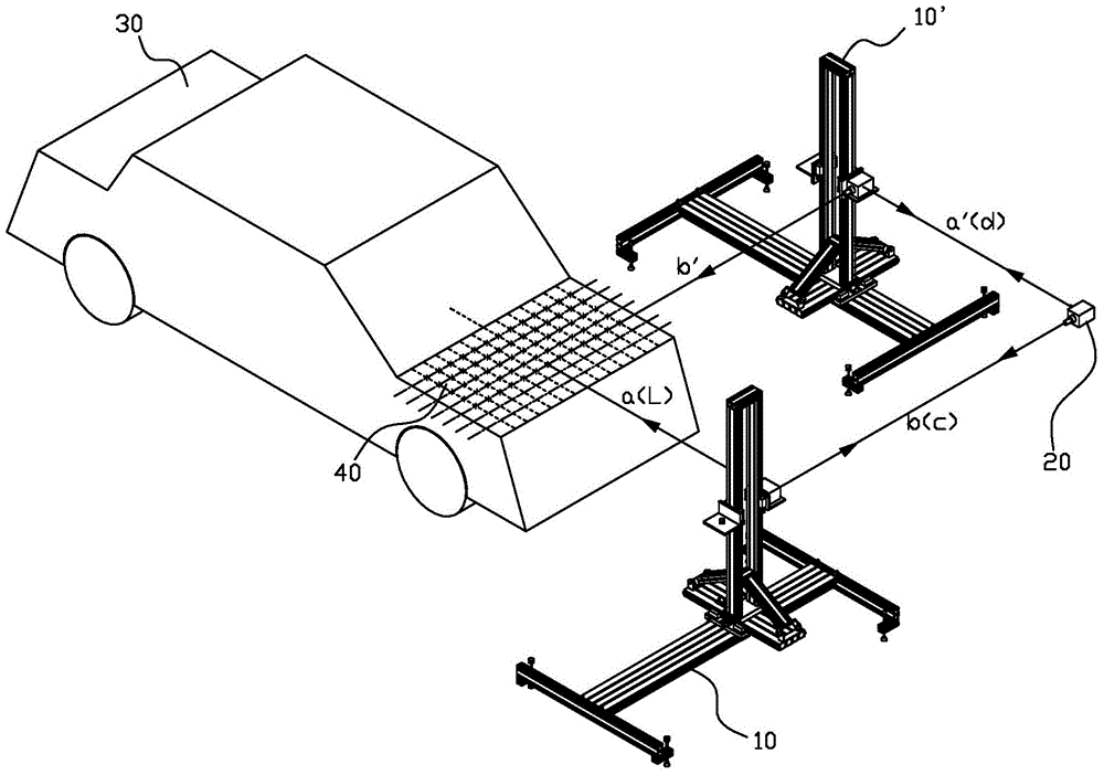
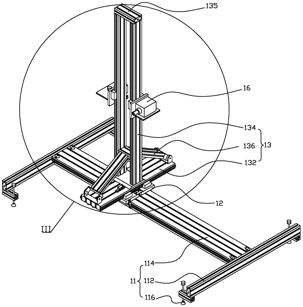
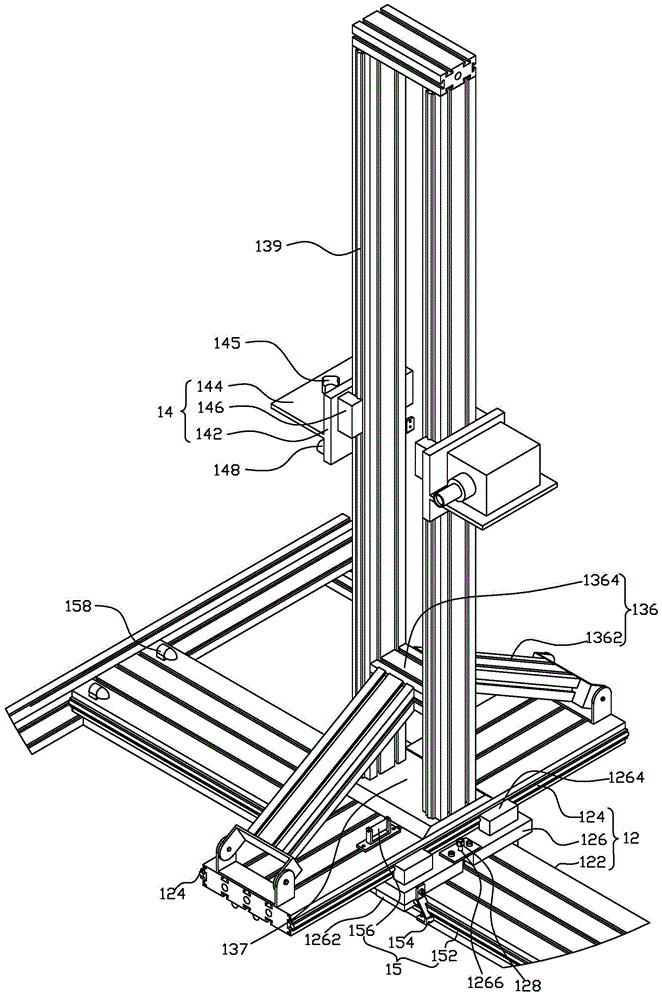
Examples


Embodiment Construction

[0023] In order to further explain the technical means and effects adopted by the present invention to achieve the intended invention purpose, the specific implementation, structure, features and effects of the present invention will be described in detail below in conjunction with the accompanying drawings and preferred embodiments.

[0024] figure 1 It is a structural schematic diagram of positioning by the laser positioning device of the present invention, figure 2 is a schematic diagram of the three-dimensional structure of the laser positioning device of the present invention, image 3 yes figure 2 The enlarged schematic diagram of middle III, Figure 4 It is a schematic diagram of a magnetic scale and a magnetic sensor. figure 1 In addition to the laser positioning device 10, it also includes an auxiliary laser instrument 20, a car 30, and a calibration grid 40. For details, please refer to Figure 1 to Figure 3 As shown, the laser positioning device 10 of the pres...


PUM


Abstract

The invention provides a laser positioning device. The laser positioning device comprises a horizontal support frame, a sliding mechanism, a vertical support, a laser instrument mounting plate, a displacement measuring device and a laser instrument, wherein the horizontal support frame comprises two horizontal and parallel cross beams and a horizontal connecting beam for connecting the two cross beams; the sliding mechanism is limited on the connecting beam in a clamping mode and can move in the direction of the connecting beam; the vertical support is fixed on the sliding mechanism and extends upwards; the laser instrument mounting plate is limited to the vertical support in the clamping mode and can move up and down along the vertical support; the laser instrument is mounted on the laser instrument mounting plate; the displacement measuring device comprises a magnetic railing ruler, a magnetic sensor and a data display screen, the magnetic railing ruler is arranged on the side wall of one side of the front side and the rear side of the connecting beam, the magnetic sensor is fixed on the sliding mechanism and can move along with the sliding mechanism, the magnetic sensor is in contact with the magnetic railing ruler, the data display screen is electrically connected with the magnetic sensor, and the magnetic sensor is used for recording the displacement along the magnetic railing ruler and transmitting the displacement to the data display screen for displaying.

Description

technical field [0001] The invention relates to the technical field of automobile collision tests, in particular to a laser positioning device. Background technique [0002] With the development of society, automobiles, as a means of transportation, have begun to enter thousands of households, and the safety performance of automobiles as a means of transportation has also attracted people's attention. It is required that once a car collides with a pedestrian, it can effectively protect the safety of the pedestrian. In response to this, my country has implemented the national standard (GB / T 24550-2009) of "Collision Protection of Automobiles to Pedestrians" on July 1, 2010, and various automobile manufacturing companies have carried out a large number of automobile side collisions for this purpose. Experiment to improve car safety. [0003] Before the car crash test, we need to accurately calibrate the longitudinal centerline of the car and the grid area of ​​the entire body...

Claims


Application Information

Patent Timeline
IPC IPC(8): G01C15/00G01M7/08G01M17/007
CPCG01C15/002G01M17/0078
Inventor 郑佳丽曹国华杨君张毅韩刚刘卫国吴成明冯擎峰
Owner ZHEJIANG GEELY AUTOMOBILE RES INST CO LTD
Learn More