Lamination anti-twist device

A lamination and anti-torsion technology, applied in the mechanical field, can solve the problems that the installation side should not bear axial load and radial load, the 4 bolts on the planetary wheel installation side are overloaded, and the test load of the rotor shaft is large, etc., to achieve Large torsional rigidity, simple assembly, and easy processing and production

Active Publication Date: 2017-05-10
CHINA AVIATION POWER MACHINE INST
View PDF10 Cites 0 Cited by
  • Summary
  • Abstract
  • Description
  • Claims
  • Application Information

AI Technical Summary

Problems solved by technology

Using the anti-torsion plate 6 to stop the torsion will cause the planetary wheel mounting side 4 to bear additional axial and radial loads, which is inconsistent with the actual flight only being subjected to torque loads, and may easily cause the planetary wheel mounting side 4 bolts to be overloaded
[0004] The test load of the rotor shaft is large, and the mounting edge 4 of the planetary gear has a certain axial and radial displacement, but the mounting edge should not bear axial load and radial load, and only bear torque load

Method used


Image

  • Lamination anti-twist device
  • Lamination anti-twist device
  • Lamination anti-twist device

Examples


Embodiment 1

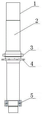
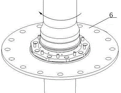
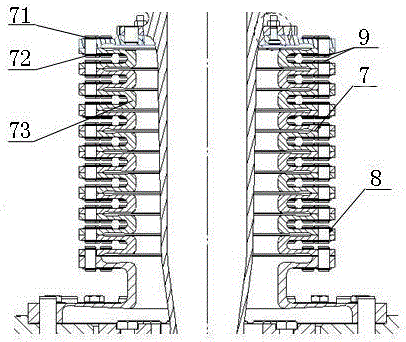
[0025] In this embodiment, the device is applied to a certain type of rotor shaft planetary gear to prevent torsion, such as figure 1 shown; as image 3 As shown, the lamination anti-torsion device of this embodiment includes a plurality of laminations 7, the laminations 7 are annular, the laminations 7 are stacked together, and the laminations 7 are connected by pins 8 and retaining rings 9; The lamination 7 includes an upper surface 71, a lower surface 72 and a connecting portion 73 connecting the upper surface 71 and the lower surface 72, the upper surface 71 is connected to the lower surface 72 of the previous lamination 7, and the lower surface 72 is connected to the lower surface 72. The upper surface 71 of one lamination 7 is connected; the upper surface 71 of the lamination 7 at the top is fixed to the component to be tested by a fastener.

[0026] Further, the connecting portion 72 is an arc-shaped structure concaved inwardly along the radial direction of the laminat...

Embodiment 2

[0033] In this embodiment, the device is applied to a certain type of rotor shaft planetary gear to prevent torsion, such as figure 1 shown; as image 3 As shown, the lamination anti-torsion device of this embodiment includes a plurality of laminations 7, the laminations 7 are annular, the laminations 7 are stacked together, and the laminations 7 are connected by pins 8 and retaining rings 9; The lamination 7 includes an upper surface 71, a lower surface 72 and a connecting portion 73 connecting the upper surface 71 and the lower surface 72, the upper surface 71 is connected to the lower surface 72 of the previous lamination 7, and the lower surface 72 is connected to the lower surface 72. The upper surface 71 of one lamination 7 is connected; the upper surface 71 of the lamination 7 at the top is fixed to the component to be tested by a fastener.

[0034] Further, the connecting portion 72 is an arc-shaped structure concaved inwardly along the radial direction of the laminat...


PUM


Abstract

The invention provides a laminated sheet twist-locking device, comprising a plurality of laminated sheets. The laminated sheets are of a ring shape and are laminated together and connected with pins and retainer rings; each laminated sheet comprises an upper surface, a lower surface and a connecting part for connecting with the upper and lower surfaces; the upper surface is connected with the lower surface of the previous laminated sheet and the lower surface is connected with the upper surface of the next laminated sheet; and the upper surface of the laminated sheet at the topmost end is fixed with a to-be-tested part through a fastener. The laminated sheet twist-locking device does not bright axial and radial constraints to the planetary gear mounting edge of a rotor shaft and is capable of bearing large torque load, so that the correct stressing state of the bolts of the mounting edge is guaranteed; the non-normal damage mode in the testing is avoided and the validity of the testing examination is guaranteed.

Description

technical field [0001] The invention relates to the field of machinery, and more specifically, to a lamination anti-torsion device. Background technique [0002] The structure diagram of a certain type of rotor shaft is as follows: figure 1 As shown, 1 is the rotor center, 2 is the rotor shaft, 3 is the cylindrical roller bearing, 4 is the mounting edge of the planetary wheel, and 5 is the angular contact ball bearing; the test load is applied to the rotor shaft center 1, and the cylindrical roller bearing 3 provides radial To the constraints, the planet wheel mounting edge 4 provides torque constraints, and the angular contact ball bearing 5 provides axial and radial constraints. The rotor shaft transmits torque through the planetary gear during flight, and the planetary gear does not bear axial force and bending moment load. [0003] For the anti-torsion on the installation side of the planetary gear, the existing technology usually uses a tie rod or anti-torsion plate t...

Claims


Application Information

Patent Timeline
Patent Type & Authority Patents(China)
IPC IPC(8): G01M13/00
Inventor 谢寒冰许炼
Owner CHINA AVIATION POWER MACHINE INST
Why Eureka
Try Eureka