Transmission line protective device

A protection device and transmission line technology, applied in overhead installation, cable installation, optical fiber/cable installation, etc., can solve the problems of falling off protection steel strands, optical cables, etc., avoid repeated replacement, good waterproof performance, and use long life effect

Active Publication Date: 2015-03-11
四川欣和嘉盛信息技术有限公司
View PDF6 Cites 4 Cited by
  • Summary
  • Abstract
  • Description
  • Claims
  • Application Information

AI Technical Summary

Problems solved by technology

However, the transmission line protection device of this patent has a shortcoming that only when the pole is toppled in a fixed direction, the base of the detacher and the splint of the steel strand can effectively fall off, and the protection of the steel strand cannot be achieved when the pole is toppled in other directions. , The role of optical cable

Method used


Image

  • Transmission line protective device
  • Transmission line protective device
  • Transmission line protective device

Examples


Embodiment 1

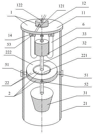
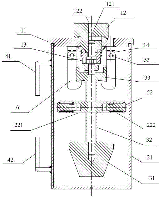
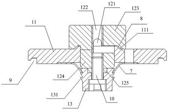
[0032] Such as figure 1 As shown, a transmission line protection device includes a steel strand splint 1 for fixing the steel strand, a disconnector base 2, and a positioning pendant assembly suspended at the lower end of the steel strand splint 1 .

[0033] The disconnector base 2 includes a cylindrical hollow body 21 and a universal rotation mechanism 22 arranged in the hollow body 21; the upper end of the hollow body 21 is in contact with the lower surface of the steel strand splint 1, and the lower end is closed However, drainage holes or drainage grooves are reserved;

[0034] The universal rotation mechanism 22 is partly connected to the central cylinder 21 and partly connected to the positioning suspension hammer assembly, which is configured to keep the positioning suspension hammer assembly in a vertical state when the central cylinder 1 is tilted at any state.

[0035] When in use, the hollow cylinder 21 is vertically fixed on the pole, the steel strand splint 1 is ...

Embodiment 2

[0038] On the basis of Embodiment 1, in this embodiment, the lower end of the steel strand splint 1 is also hinged with a plurality of hooks 6, and the hooks 6 can move in a direction consistent with the radial direction of the hollow cylinder 21, that is, its When moving, the lower end moves towards the central axis of the hollow cylinder 21 or away from the central axis of the hollow cylinder 21;

[0039] The positioning suspension hammer assembly includes a suspension hammer arm 32, a suspension mechanism 33 connected to the upper end of the suspension hammer arm 32, and a gravity suspension hammer 31 fixed at the lower end of the suspension hammer arm 32; the suspension mechanism 33 is suspended on the hook 6, and a plurality of The hooks 6 are evenly distributed on the side of the suspension mechanism 33, and hook the suspension mechanism 33 from different directions. In this embodiment, the suspension mechanism 33 is a cylindrical mechanism with a vertical axis. In pract...

Embodiment 3

[0043] On the basis of Embodiment 2, in this embodiment, the universal rotating mechanism 22 is further improved, and the universal rotating mechanism 22 includes a first turntable 221 arranged inside the hollow cylinder 21, and a first turntable 221 arranged outside the first turntable 221. The annular second turntable 222 of. The inner diameter of the second turntable 222 is larger than the radius of the first turntable 221. The second turntable 222 is sheathed outside the first turntable 221, and its inner peripheral surface faces the first turntable 221. The central axes of the two turntables coincide.

[0044] Both sides of the second turntable 222 are respectively connected to the hollow cylinder 21 by a fastener A51, and both sides of the first turntable 221 are respectively connected to the second turntable 222 by a fastener B52. In this embodiment The fastener A51 and the fastener B52 use bolts, and other commonly used fasteners, such as but not limited to pin shafts ...


PUM


Abstract

The invention discloses a transmission line protective device. The transmission line protective device comprises a steel strand clamping plate, a disconnector pedestal, a positioning suspending hammer component hung at the lower end of the steel strand clamping plate, and an electric pole connecting mechanism arranged on the disconnector pedestal, wherein the disconnector pedestal comprises a hollow barrel and a universal rotating mechanism arranged inside the hollow barrel; the upper end of the hollow barrel is in contact with the lower surface of the steel strand clamping plate; part of the universal rotating mechanism is connected with a central barrel, and the other part of the universal rotating mechanism is connected with the positioning suspending hammer component; the positioning suspending hammer component can be kept vertical when the central barrel is inclined randomly. With application of the transmission line protective device disclosed by the invention, when the electric pole is toppled in any direction, the steel strand and the cable can be detached from the electric pole, so as to protect the steel strand and the cable from snap; the transmission line protective device has the advantages of convenient installation, good waterproofness and long service life.

Description

technical field [0001] The invention relates to the technical field of line protection, in particular to a transmission line protection device. Background technique [0002] Aerial optical cable transmission is composed of steel strands, optical cables, inductors, splints, hoops and hooks. Steel strands are used to suspend optical cables. fixed. [0003] Natural disasters such as landslides and mudslides occur frequently all over the world every year, causing a large number of electric poles to fall, steel strands to be broken, and optical cables to be broken, resulting in large-scale communication interruptions. The emergence of such problems not only affects business and causes economic losses, but also brings great inconvenience to emergency command and maintenance. In consideration of the personal safety of the maintenance personnel, when a natural disaster occurs, personnel are usually not dispatched for on-site repair immediately. Due to the uncertainty of the occurr...

Claims


Application Information

Patent Timeline
Patent Type & Authority Applications(China)
IPC IPC(8): G02B6/48H02G7/00
CPCG02B6/483H02G7/00
Inventor 曾祥
Owner 四川欣和嘉盛信息技术有限公司
Why Eureka
Try Eureka