Novel adjustable resonator
An adjustable and resonator technology, applied in the direction of resonators, waveguide devices, electrical components, etc., can solve the problems of high manufacturing cost, poor mechanical stability, poor tunability, etc., and achieve low manufacturing cost, tunability and mechanical Good stability and simple structure
- Summary
- Abstract
- Description
- Claims
- Application Information
AI Technical Summary
Problems solved by technology
Method used
Image

Examples
Embodiment Construction
[0015] combined with picture , the invention is described in further detail.
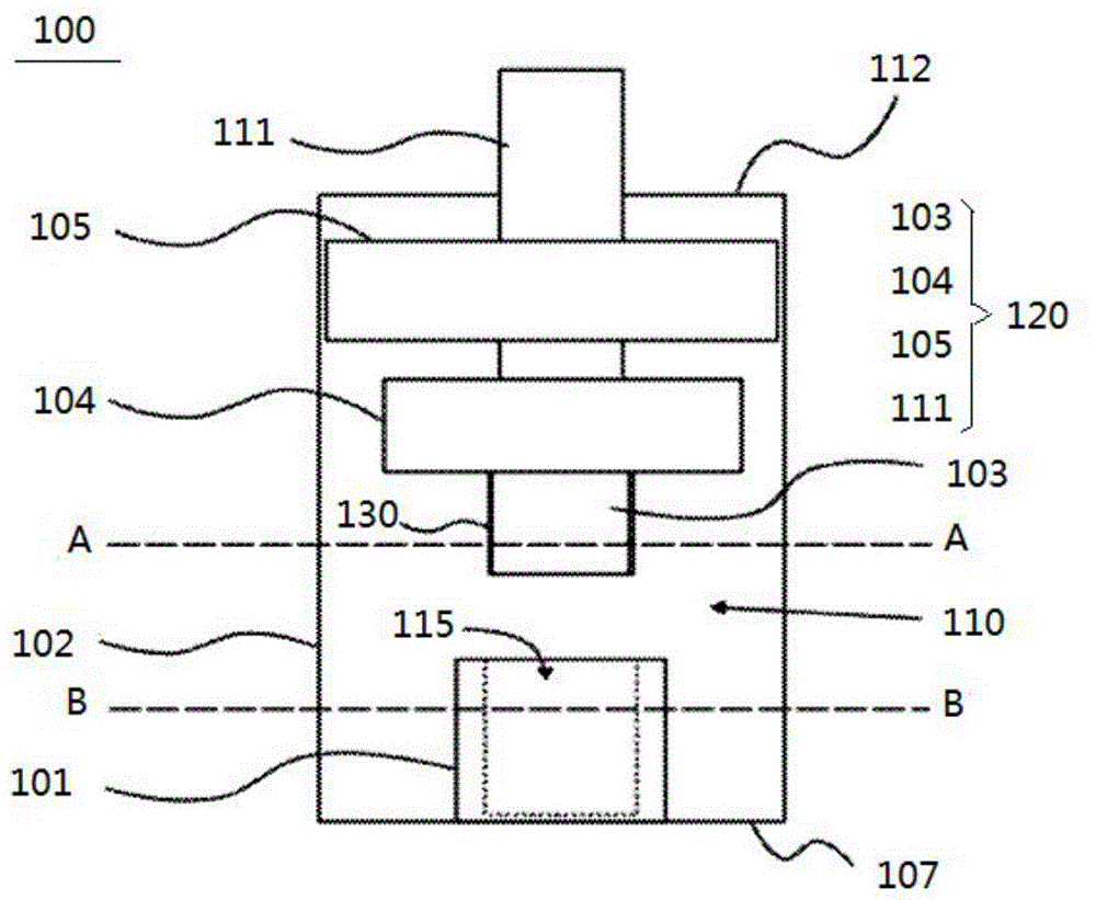
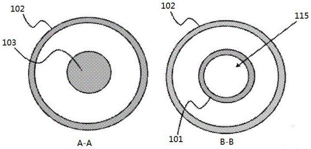
[0016] see picture 1, picture 2. The adjustable resonator 100 of this embodiment includes a housing and a fixed inner conductor 101, the housing is composed of a housing wall 102, a housing bottom 107 and a housing cover 112; wherein the housing is at least partially made of conductive material And the interior is a resonant cavity 110 , and the inner conductor 101 is electrically connected to the shell bottom 107 .
[0017] The adjustable resonator 100 further includes a movable resonant frequency adjustment member 120, the resonant frequency adjustment member 120 includes a cylindrical conductive adjustment element, a conductive upper plate 105 and a dielectric support element 111, wherein the main body of the conductive adjustment element is longitudinal Conductive valve stem 103, the upper end of the conductive valve stem 103 is provided with a conductive cap 104; the conductive valve stem...
PUM
 Abstract
Description
Claims
Application Information