
drill chuck

一种钻夹头、夹爪的技术,应用在机械加工用刀具的夹具领域,能够解决易过大破坏刀具、钻夹头不方便打开等问题,达到避免费劲甚至打不开的效果

Active Publication Date: 2016-06-29
WEIHAI DAWANG HARDWARE PROD
View PDF6 Cites 1 Cited by
  • Summary
  • Abstract
  • Description
  • Claims
  • Application Information

AI Technical Summary

Problems solved by technology

[0007] The present invention aims at the technical problem that the clamping force of the existing drill chuck is too large to easily damage the tool and make the drill chuck inconvenient to open, and provides a drill chuck that can protect the tool and is convenient to open

Method used


Image

  • drill chuck
  • drill chuck
  • drill chuck

Examples


Embodiment Construction

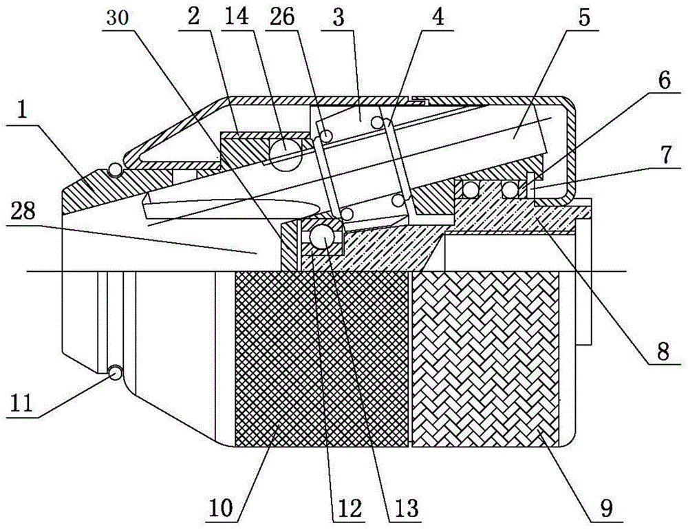
[0026] Such as figure 1 As shown, the present invention mainly includes a front body 1, a rear body 8, a front cover 10, a rear cover 9, jaws 5, and a driven gear 3. The rear body 8 is built in the front body 1 and can only rotate laterally relative to the front body 1 . The front body 1 is provided with a jaw hole 15 , and the jaw 5 is located in the jaw hole 15 . The driven gear 3 is provided with an internal thread, which cooperates with the outer peripheral thread of the jaw 5. The lower end of the rear body 8 is provided with a driving gear 19, and the driving gear 19 cooperates with the driven gear 3. When the rear body 8 rotates , the driven gear 3 also rotates, and the jaw 5 moves up and down driven by the gear 3 .

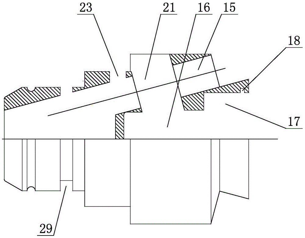
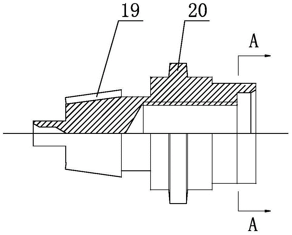
[0027] Such as Figure 2 to Figure 4 As shown, a front groove 16 and a rear groove 17 are provided at the center of the rear end of the front body 1 , and when the rear body 8 is inserted into the front body 1 , the rear body 8 just fits with these two ...


PUM


Abstract

The present invention provides a drill chuck, which solves the original problem of inconvenient opening and easy damage to the tool due to too much clamping force of the drill chuck. There are threads, the rear body is provided with a driving gear, and a driven gear is provided between the jaws and the rear body, the driving gear and the driven gear cooperate with each other, and the driven gear is provided with threads inside, and the threads cooperate with the threads of the jaws The invention can be widely used in the field of mechanical processing.

Description

technical field [0001] The invention relates to a tool clamp for mechanical processing, in particular to a drill chuck which is easy to open and protects the tool. Background technique [0002] In production and processing activities, tools such as machine tools and electric drills are often used for drilling, milling and other operations. Although the drill chucks installed on the working axes of these equipment hosts to hold drills, milling cutters and other tools have experienced long-term application and improvement , but there are still many deficiencies. Judging from the source of the force in the drill chuck that pushes the jaws to move up and down in the jaw hole, the drill chuck is mainly divided into the following three types: [0003] First, the drill chuck that gives the force to move the jaws up and down from the outside of the jaws. This kind of drill chuck generally has a local thread on the outside of the jaws. This thread cooperates with the thread on the ...

Claims


Application Information

Patent Timeline
Patent Type & Authority Patents(China)
IPC IPC(8): B23B31/11B23B31/165
CPCB23B31/1207B23B31/1215B23B2260/07B23B2260/106Y10T279/17666B23B31/16083B23B2231/24
Inventor 柳尧亭于作滋
Owner WEIHAI DAWANG HARDWARE PROD
Learn More