printing press

A technology of printing presses and gears, applied in printing presses, printing, rotary printing presses, etc., can solve problems such as increasing work preparation time

Active Publication Date: 2018-04-10
HEIDELBERGER DRUCKMASCHINEN AG
View PDF7 Cites 0 Cited by
  • Summary
  • Abstract
  • Description
  • Claims
  • Application Information

AI Technical Summary

Problems solved by technology

thus increased work preparation time

Method used


Image

  • printing press
  • printing press
  • printing press

Examples


Embodiment Construction

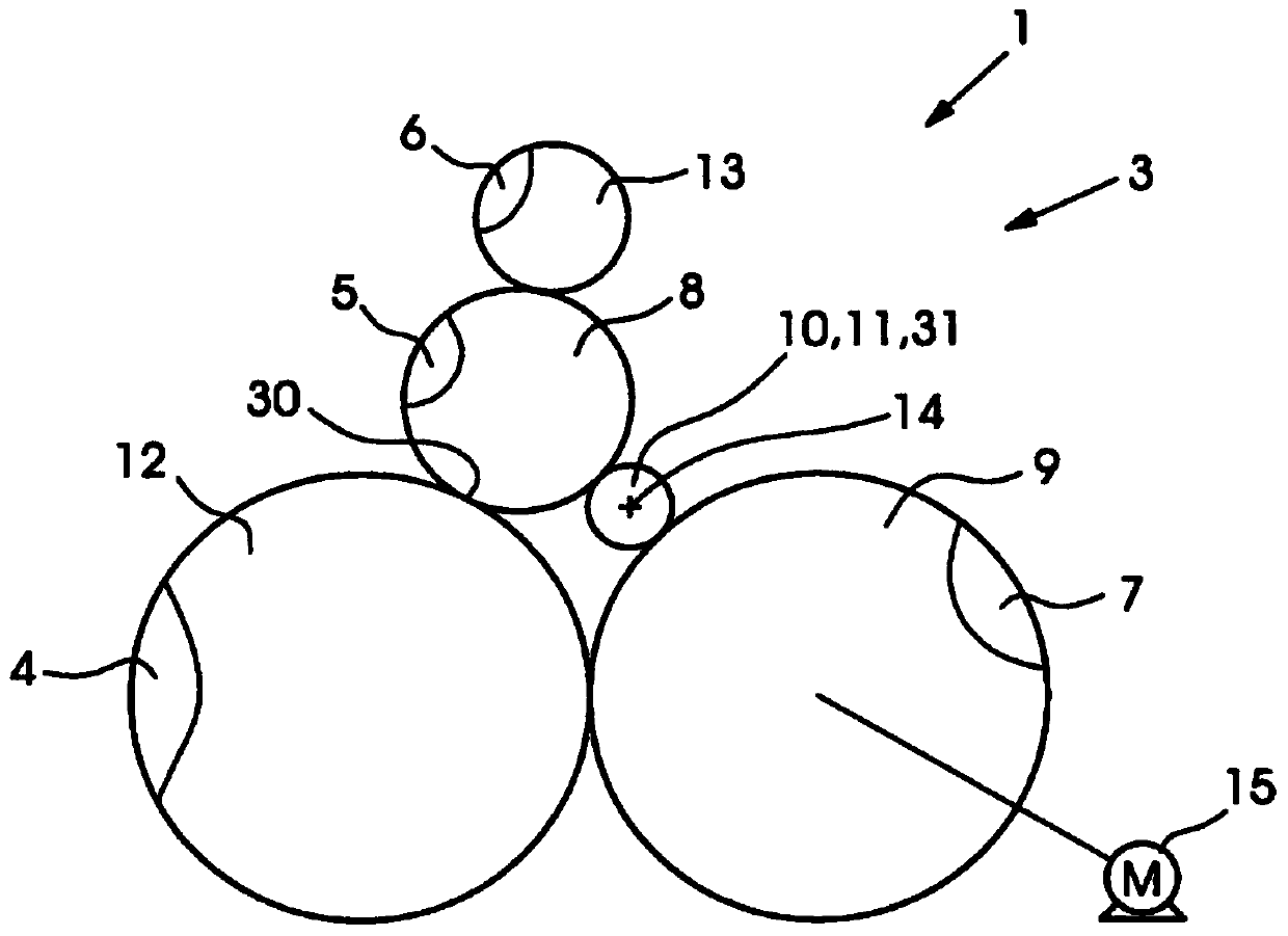
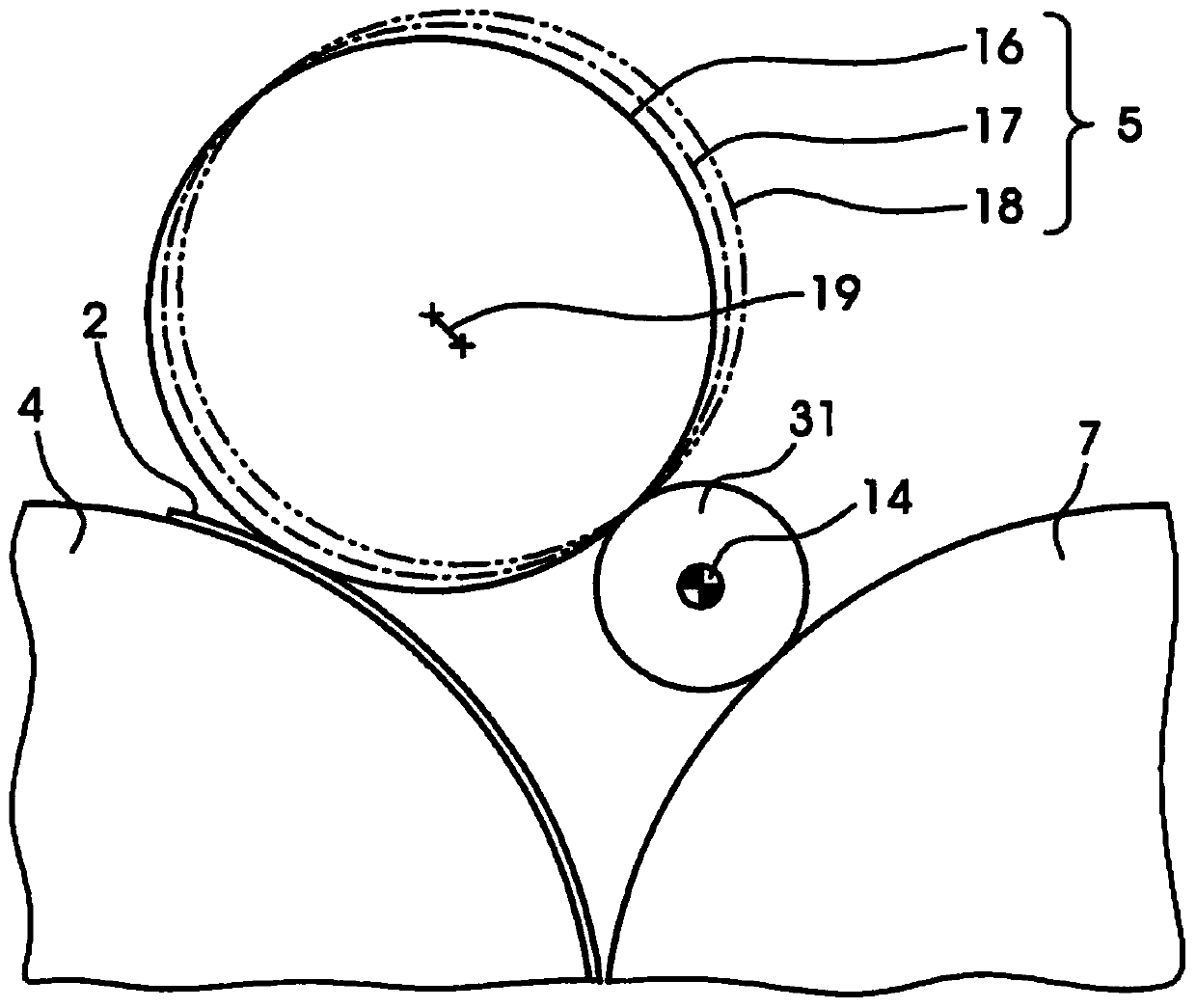
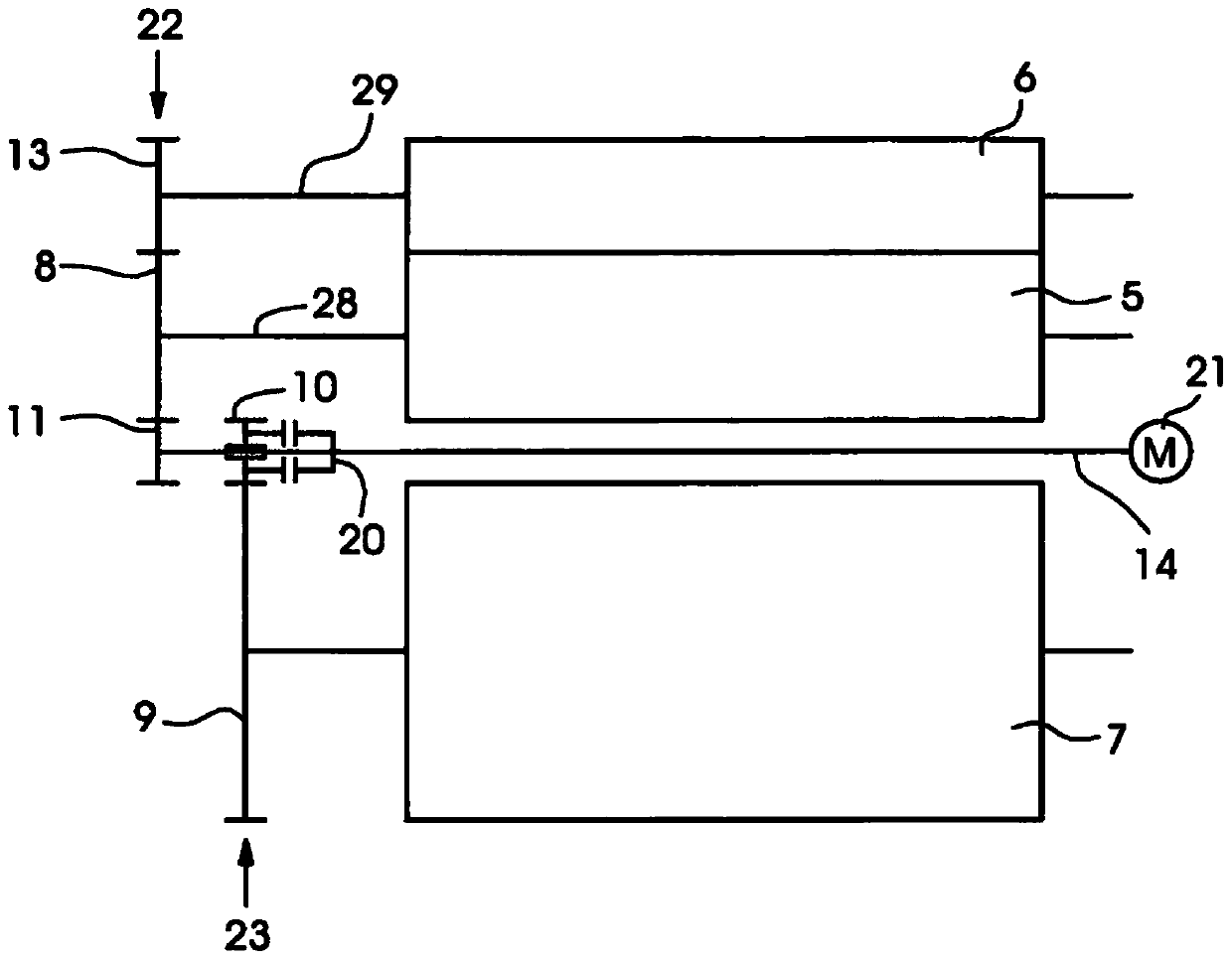
[0029] exist figure 1 A printing press 1 for offset lithographic printing on sheets 2 is shown partially in the middle. A varnishing unit 3 for varnishing a sheet 2 printed in an offset printing unit is shown in this detail. The varnishing unit 3 comprises an impression cylinder 4 for transporting the sheets 2 and an application cylinder 5 for applying varnish to the respective transported sheets 2 . During varnishing, the embossing cylinder 4 and the application cylinder 5 together form an embossing nip 30 in which a coating liquid (varnish) is transferred from the application cylinder 5 to the conveyed sheet 2 . The anilox roller 6 rests against the application cylinder 5 and supplies the varnish to this application cylinder. In the sheet transport arrangement, a sheet transport drum 7 is arranged upstream of the impression cylinder 4 , which feeds the sheets 2 one after the other onto the impression cylinder 4 . The impression cylinder 4 and the sheet transfer drum 7 are...


PUM


Abstract

The invention relates to a printing machine comprising a first cylinder (5) with a first gear (8), a second cylinder (7) with a second gear (9) and a third cylinder (4), the third The cylinder together with the first cylinder (5) forms the impression nip and receives the sheet (2) from the second cylinder (7), wherein there is an intermediate shaft (14) with a gear arrangement (31), the first gear (8) and the second gear (9) are permanently connected to each other by a gear structure (31). Preferably, the first cylinder (5) is an application cylinder (5), the second cylinder (7) is a sheet transfer drum (7) and the third cylinder (4) is an impression cylinder (4).

Description

technical field [0001] The invention relates to a printing machine, which comprises a first cylinder with a first gear, a second cylinder with a second gear, and a third cylinder, the third cylinder together with the first cylinder constitutes an impression gap and passes from the second cylinder Receive sheets. The first cylinder can in particular be an application cylinder for applying varnish or ink to the sheets, the second cylinder can be a sheet transfer drum and the third cylinder can be an impression cylinder. Background technique [0002] EP 1104858 B1 shows a printing press with a varnishing unit comprising an application cylinder with gears and an impression cylinder with gears. The application roller can be adjusted into an active position for varnish and into a passive position for other purposes. The two gears mesh with each other in the active position and do not mesh in the passive position. In the active position, the main drive drives the application rol...

Claims


Application Information

Patent Timeline
Patent Type & Authority Patents(China)
IPC IPC(8): B41F13/004B41F13/008B41F13/012
CPCB41F13/008B41F13/0045
Inventor R·金德根G·默克尔M·波斯特尔斯
Owner HEIDELBERGER DRUCKMASCHINEN AG
Why Eureka
Try Eureka