
elastic bushing

A technology of elastic bushing and elastic part, which is applied in the direction of axle box installation, device for lateral relative movement between underframe and bogie, etc., can solve the problems of low rigidity ratio and difficult realization, and achieve reasonable strength balance and stable performance , Ease of use and excellent effect

Inactive Publication Date: 2018-04-27
NITTA CHEM IND PROD CO LTD
View PDF8 Cites 0 Cited by
  • Summary
  • Abstract
  • Description
  • Claims
  • Application Information

AI Technical Summary

Problems solved by technology

However, it is difficult to achieve a low rigidity ratio of about 2 times
[0011] Therefore, in the conventional elastic bushing, it is difficult to set a low rigidity ratio that fully satisfies the requirement due to some defects in the rigidity in the axial direction in many cases.

Method used


Image

  • elastic bushing
  • elastic bushing
  • elastic bushing

Examples


Embodiment approach 1

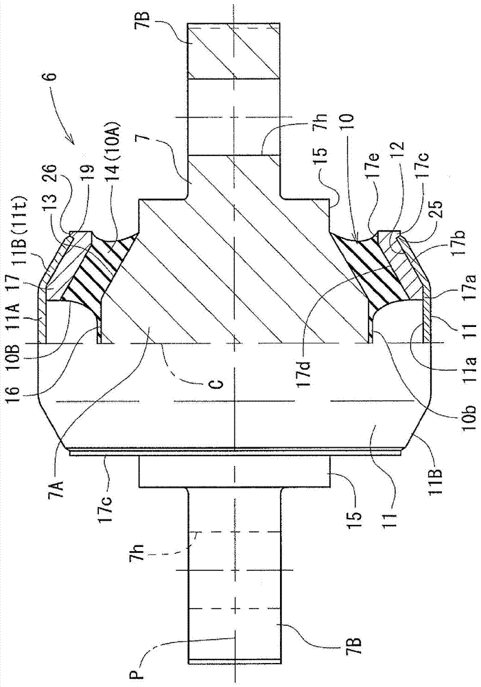
[0060] Figure 4 The outline of the axle-beam device of a railway vehicle is shown, in which 1 is an axle, 2 is an axle box part, 3 is an axle beam, 4 is a housing part, 5 is a wheel attached to the axle 1, and 6 is an elastic bushing (also known as anti-vibration bushing), 8 is a trolley frame.

[0061] The axle beam 3 extends from the axle box portion 2 for supporting the axle 1 toward the vehicle traveling direction (arrow Y direction), and the elastic bush 6 is fitted into a cylindrical cover portion 4 formed at one end of the axle beam 3 . 8A is a bifurcated support bracket for supporting the center shaft 7 of the elastic bush 6 , and is formed to protrude downward from the dolly frame 8 .

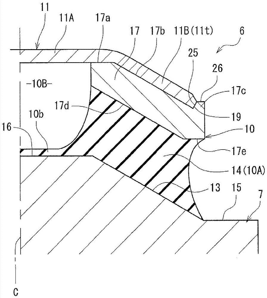
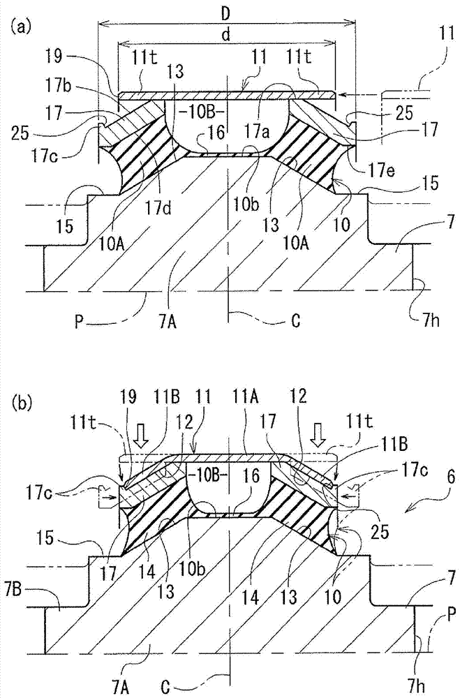
[0062] Such as Figure 4-Figure 6 As shown, the outer member 11 of the elastic bush 6 is fitted and fixed in the fitting hole 4H of the cover part 4, and although not shown, both ends of the central axis 7 of the elastic bush 6 are fixed by means of bolts. etc. are non-rotatably su...


PUM


Abstract

The invention provides an elastic sleeve capable of setting the ratio of rigidity to radial direction of an axis direction of a central shaft at the lower position, namely the rigidity ratio such that the elastic sleeve with the required lower rigidity. The elastic sleeve is provided with a central shaft equipped with an axis intersected with the travelling direction of a vehicle, an outside member arranged on the periphery of the radial outside of the central shaft and an elastic part arranged between the central shaft and the outside member in an inference mode. The elastic sleeve is characterized in that as an outer embedded part externally embedded at the position of the elastic part in the outside member, the outer embedded part is provided with an inclined inner peripheral surface with one end of the diameter which is increasingly smaller along the width direction of an axis. A part, which is embedded into the elastic part, of the central shaft is provided with an inclined outer peripheral surface which is opposite to an axis direction and in the same direction to the inclined inner peripheral surface. The elastic part is provided with a compression part compressed between the inclined inner peripheral surface and the inclined outer peripheral surface.

Description

technical field [0001] The present invention relates to an elastic bush (bush) suitable for traveling vehicles as an axle beam device of a railway trolley, and more particularly to an elastic bush (bush) having: a central shaft having an axis intersecting with the traveling direction of the vehicle; an outer member , which is disposed around the radially outer side of the central shaft; and an elastic portion, which intervenes in an elastic bush installed between the central shaft and the outer member. Background technique [0002] For example, the axle-beam device is used to fit and fix the elastic bushing, and fix the central shaft of the elastic bushing to the trolley frame (frame) in a non-rotatable manner. a cylindrical cover at one end of the axle beam at a right angle with respect to the traveling direction of the vehicle; a substantially cylindrical elastic body composed of rubber or the like arranged and adhered to the outer periphery of the central shaft; and an ou...

Claims


Application Information

Patent Timeline
Patent Type & Authority Patents(China)
IPC IPC(8): B61F5/02
CPCB61F5/36
Inventor 筱原克行
Owner NITTA CHEM IND PROD CO LTD
Learn More