
Oil cylinder driving lifting mechanism and dynamic compactor

A technology of dynamic tamping machine and oil cylinder, which is applied in cranes, infrastructure engineering, soil protection, etc., and can solve the problems of slow falling speed of rammer, loss of tamping energy, and low work efficiency of tamping the ground

Active Publication Date: 2015-03-18
河北雷萨重型工程机械有限责任公司
View PDF6 Cites 6 Cited by
  • Summary
  • Abstract
  • Description
  • Claims
  • Application Information

AI Technical Summary

Problems solved by technology

[0004] However, there are still two problems in the above-mentioned oil cylinder-driven lifting mechanism that need to be solved urgently: on the one hand, the falling speed of the rammer in the non-decoupling mode is slow due to the oil return resistance of the oil cylinder, and the loss of tamping energy reaches more than 20%. Low
On the other hand, due to the working nature of the dynamic compaction machine, the oil cylinder has to bear frequent impact and heavy loads, resulting in a high failure rate of the oil cylinder, short service life, and a large power loss due to the temperature rise of the hydraulic oil, which makes the dynamic compaction machine unable to operate continuously for a long time. Ramming operation requires intermittent downtime for maintenance and heat dissipation, resulting in low work efficiency

Method used


Image

  • Oil cylinder driving lifting mechanism and dynamic compactor
  • Oil cylinder driving lifting mechanism and dynamic compactor

Examples


Embodiment Construction

[0021] In order to make the objectives, technical solutions and advantages of the present invention clearer, the technical solutions in the embodiments of the present invention will be described in more detail below in conjunction with the drawings in the embodiments of the present invention. In the drawings, the same or similar reference numerals denote the same or similar elements or elements having the same or similar functions throughout. The described embodiments are some, but not all, embodiments of the invention. The embodiments described below by referring to the figures are exemplary and are intended to explain the present invention and should not be construed as limiting the present invention. Based on the embodiments of the present invention, all other embodiments obtained by persons of ordinary skill in the art without creative efforts fall within the protection scope of the present invention. Embodiments of the present invention will be described in detail below ...


PUM


Abstract

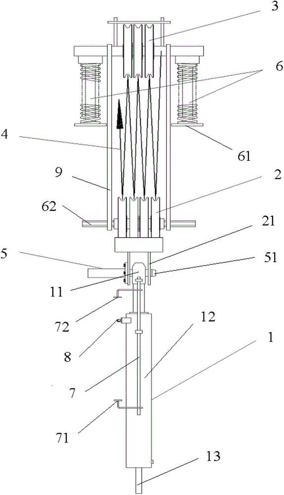
The invention discloses an oil cylinder driving lifting mechanism and a dynamic compactor. The oil cylinder driving lifting mechanism comprises a fixed pulley block, a movable pulley block, a lifting rope, a driving oil cylinder and an automatic connection device, wherein a first end of the driving oil cylinder is connected with a vehicle body of the dynamic compactor; a second end of the driving oil cylinder is connected with the movable pulley block in a removable manner; and when the second end of the driving oil cylinder moves to a connection position from a disconnection position, the automatic connection device is disconnected from the second end of the driving oil cylinder and is connected with the movable pulley block. After the movable pulley block is driven to a set position which corresponds to the disconnection position, the driving oil cylinder can be connected with the movable pulley block in the removable manner, and a pounder is released to perform tamping. Tamping energy loss caused by the driving oil cylinder is avoided.

Description

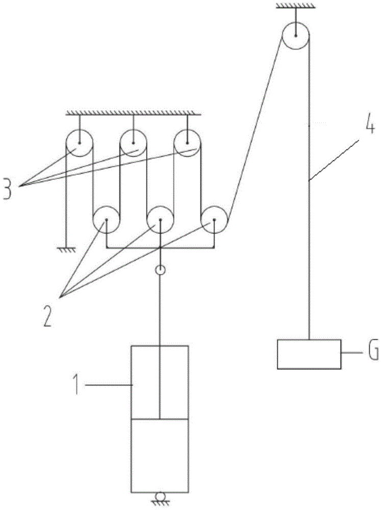
technical field [0001] The invention relates to the technical field of engineering machinery, in particular to an oil cylinder-driven lifting mechanism and a dynamic compaction machine. Background technique [0002] In the existing lifting technology of dynamic tamping machines, there are mainly two solutions: the traditional winch lifting mechanism and the cylinder-driven lifting mechanism applied in recent years. The hoisting mechanism is mainly composed of motors (electric motors or hydraulic motors), reducers, clutches, drums, brakes and other components. The mechanism is complex, the reliability is poor, and the manufacturing and maintenance costs are high. [0003] figure 1 It is a schematic diagram of the cylinder-driven lifting mechanism in the prior art. exist figure 1 In the cylinder-driven lifting mechanism shown, the drive cylinder 1 expands and contracts to drive the movable pulley block 2 to move relative to the fixed pulley block 3, and the movable pulley b...

Claims


Application Information

Patent Timeline
Patent Type & Authority Applications(China)
IPC IPC(8): E02D3/046B66C23/36
CPCB66C23/36E02D3/046
Inventor 郭立波孙守和蔡淳李殿浦陈志刚
Owner 河北雷萨重型工程机械有限责任公司
Learn More