
Computed tomography user interface and working method thereof

A user interface and tomography technology, applied in computing, instrumentation, electrical and digital data processing, etc., can solve the problem of displaying sub-time progress bars, and achieve reliable control and improve user experience.

Inactive Publication Date: 2015-03-18
SHANGHAI UNITED IMAGING HEALTHCARE
View PDF5 Cites 2 Cited by
  • Summary
  • Abstract
  • Description
  • Claims
  • Application Information

AI Technical Summary

Problems solved by technology

[0004] The invention solves the problem that it is difficult to clearly display each sub-time progress bar in the display area of ​​the existing computer tomography user interface

Method used


Image

  • Computed tomography user interface and working method thereof
  • Computed tomography user interface and working method thereof

Examples


Embodiment Construction

[0017] In order to make the above objects, features and advantages of the present invention more comprehensible, specific implementations of the present invention will be described in detail below in conjunction with the accompanying drawings.

[0018] figure 1 It is a schematic diagram of the time progress bar of the computed tomography scan of the present invention, and the user interface of the computed tomography scan may include multiple sub-interfaces, for example: patient management interface, image browsing interface, printing interface, scanning interface and the like. When performing computed tomography, the display area of ​​the user interface usually displays the scanning interface (at this time, other sub-interfaces are running in the background and are not displayed in the display area, and the user can also call other sub-interfaces to display them in the display area), so The scanning interface includes at least one time progress bar, and may also include parts...


PUM


Abstract

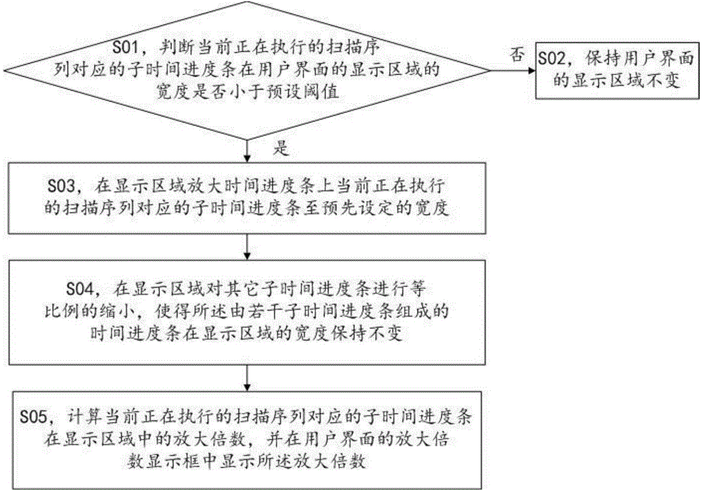
The invention discloses a computed tomography user interface and a working method thereof. When a scanning protocol is executed, a sub-time progress bar is amplified to a preset width if the width of the sub-time progress bar corresponding to a currently executed scanning sequence at a display region of the user interface is smaller than a preset threshold value; other sub-time progress bars are scaled down at the display region, so the width of the time progress bar consisting of a plurality of sub-time progress bars at the display region is kept unchanged; the amplification factor of the sub-time progress bar corresponding to the executed scanning sequence in the display region is calculated, and the amplification factor is displayed in an amplification factor display frame of the user interface. According to the computed tomography user interface, a user can clearly observe the sub-time progress bar corresponding to each currently executed scanning sequence during scanning, so that the user experience is improved.

Description

【Technical field】 [0001] The invention relates to the technical field of computed tomography (CT), in particular to a computer tomography user interface and a working method thereof. 【Background technique】 [0002] In the process of performing computed tomography, performing a scan usually needs to be completed by executing a scan protocol. A scan protocol includes multiple scan sequences that need to be executed sequentially. During scanning, a time progress bar will be displayed on the user interface, and the time progress The bar is mainly used to display the execution progress of the scanning protocol. The time progress bar includes several sub-time progress bars corresponding to several scanning sequences. Each sub-time progress bar occupies a small space, so it is often difficult for the user to pass the Each sub-time progress bar can be clearly seen in the display area of ​​the interface, so it is difficult to easily grasp the progress of the scanning sequence current...

Claims


Application Information

Patent Timeline
Patent Type & Authority Applications(China)
IPC IPC(8): G06F3/0481
CPCG06F3/04817G06F2203/04806H04N21/47217H04N21/8456
Inventor 孙洪雨
Owner SHANGHAI UNITED IMAGING HEALTHCARE
Learn More