
Automatic fail preventing device for ceramic filter

A technology of ceramic filters and ceramic filter tubes, which is applied in the fields of dispersed particle filtration, chemical instruments and methods, and separation of dispersed particles. Sex and continuity, easy operation and installation, and the effect of improving operating costs

Inactive Publication Date: 2015-03-25
NORTH CHINA ELECTRIC POWER UNIV (BAODING)
View PDF6 Cites 4 Cited by
  • Summary
  • Abstract
  • Description
  • Claims
  • Application Information

AI Technical Summary

Problems solved by technology

But, there are following problems in this online monitoring alarm system: 1, the cost is very high
In industrial applications, ceramic filters have as many as thousands of filter elements. If an online monitoring probe is added to each filter element, the cost of the entire ceramic filter will be greatly increased, which is not conducive to large-scale application
2. Low monitoring accuracy
However, it is more difficult to find out where the faulty component is located from the continuous static differential pressure monitoring chart
And, due to the need for continuous filter-backflush cycles in operation, the change in pressure difference will become more complicated
Therefore, misjudgment, missed judgment and delayed judgment often occur in the monitoring of faults, and it is difficult to accurately locate and control the damaged filter element
3. Low running stability
As long as there is an alarm, it will automatically shut down. In the actual operation process, the ceramic filter tube is a brittle component with a high breakage rate. Therefore, if this online monitoring and alarm system is used, the ceramic filter will be shut down for a long time to replace components. The continuity of the entire filtration system is poor and the operation stability is low

Method used


Image

  • Automatic fail preventing device for ceramic filter
  • Automatic fail preventing device for ceramic filter
  • Automatic fail preventing device for ceramic filter

Examples


Embodiment Construction

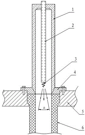
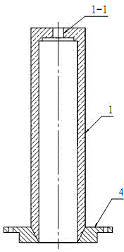
[0029] see figure 1 , figure 2The device of the present invention is provided with a porous metal protective tube 1 made of porous metal, and the porous metal protective tube is fixed on the upper part of the filter main plate 5, and its position corresponds to the ceramic filter tube 6 up and down. The upper end of the porous metal protection tube is provided with an inlet hole 1-1 for installing the injection tube 2, and the inlet hole of the injection tube is matched with the injection tube. Welding, screw holes are provided on the fixing seat, the fixing seat is positioned on the filter main plate by the positioning screw, and the lower end surface of the fixing seat is flush with the upper end surface of the filter element.

[0030] see figure 1 , image 3 , the lower part of the spray pipe 2 is located in the porous metal protection tube, and the top of the spray pipe protrudes from the porous metal protection tube. The lower end of the blowing pipe is provided with...


PUM


Abstract

The invention provides an automatic fail preventing device for a ceramic filter. The automatic fail preventing device for the ceramic filter comprises a porous metal protection pipe and a fixing seat, wherein the porous metal protection pipe is fixed at the upper part of a main pipe plate of the filter through the fixing seat, and the position of the porous metal protection pipe corresponds to that of a ceramic filtering pipe up and down; an injecting and blowing pipe is arranged in the porous metal protection pipe, the upper end of the injecting and blowing pipe extends out of the top of the porous metal protection pipe and is communicated with a back flushing distribution pipe, and a spiral drain pump is arranged at the lower end of the injecting and blowing pipe. According to the automatic fail preventing device for the ceramic filter, the pressure drop is relatively low when the ceramic filter safely runs, cleaning gas can smoothly enter an air purification room through the wall of the protection pipe; when a filtering element has failure, large-particle dust can be quickly sealed so as to prevent an integral system from stopping caused by the damage of few of filtering elements. The automatic fail preventing device for the ceramic filter automatically seal damaged filtering elements, and a precise online monitoring device and a corresponding probe for locating the damaged filtering elements do not need to be installed, so that the operation and the installation are convenient, and the error stopping caused by error judgment is also avoided.

Description

technical field [0001] The invention relates to an accessory device of a ceramic filter, which can automatically protect the filter when a ceramic filter tube breaks down, so as to prevent leakage accidents. Background technique [0002] Petroleum, chemical industry, metallurgy, electric power and other industries will produce various high-temperature dust-containing gases during operation. In order to meet the national emission standards, these high-temperature dust-containing gases must be dedusted. High-temperature gas dedusting is a technology that directly separates gas from solid under high-temperature conditions to achieve gas purification. The high-temperature gas dedusting technology can directly dedust at high temperature without the need for heat exchangers and other peripheral equipment, which can effectively improve energy utilization, simplify the process, and save equipment investment. The most promising application of high temperature dust removal technology...

Claims


Application Information

Patent Timeline
IPC IPC(8): B01D46/24B01D46/42
Inventor 赵毅刘侃
Owner NORTH CHINA ELECTRIC POWER UNIV (BAODING)
Learn More