Liquid flinging device

A technology of liquid rejection and liquid rejection plate, which is applied in the direction of combined device, liquid separation agent, membrane technology, etc., can solve the problems of non-adjustable movement direction, poor purification effect, and inability to produce particle size distribution mode, etc., to achieve the goal of purification effect Effect

Active Publication Date: 2015-03-25
伟复环保科技(北京)有限公司
View PDF12 Cites 20 Cited by
  • Summary
  • Abstract
  • Description
  • Claims
  • Application Information

AI Technical Summary

Problems solved by technology

[0002] It is pointed out in related technologies that droplets of different particle sizes in wet dust removal have higher removal efficiency for pollutants of different particle sizes, that is to say, each particle size of pollutants corresponds to an optimal particle size However, in the purification method in the related art, the droplets used for purification cannot produce a specific particle size distribution pattern, and the particle size distribution range cannot be precisely controlled as required. For example, 500 microns to 1000 microns are often used in the related art The liquid droplets of about micron are used for purification, the particle size distribution range of the droplets is small, and the removal efficiency of particulate matte

Method used


Image

  • Liquid flinging device
  • Liquid flinging device
  • Liquid flinging device

Examples


Embodiment 1

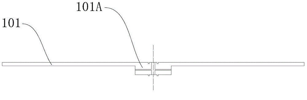
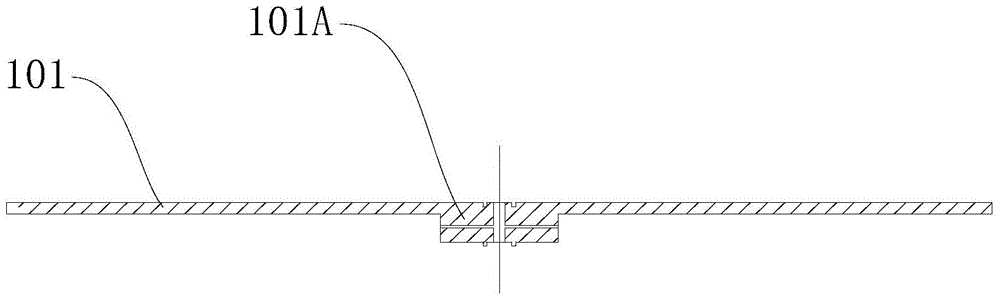
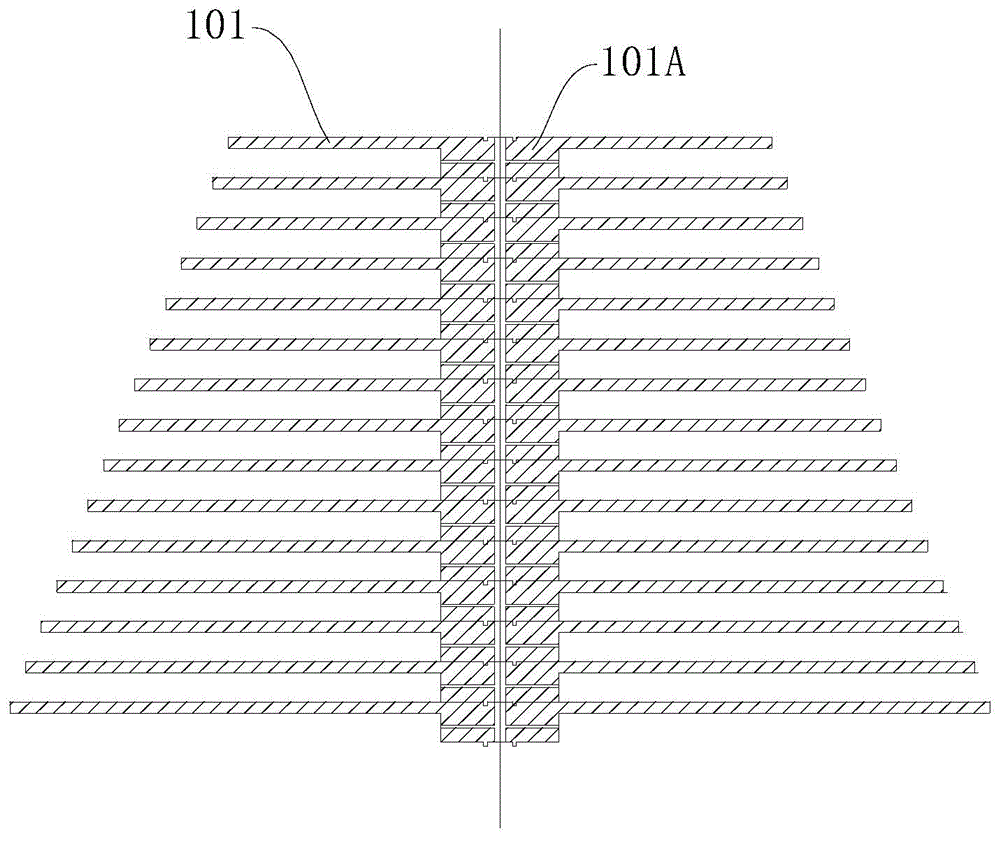
[0072] like Figure 1-Figure 4 As shown, the liquid rejection assembly includes a rotating shaft 101A and at least one liquid rejection disk 101, at least one liquid rejection disk 101 is detachably connected to the rotation shaft 101A, wherein at least one liquid rejection disk 101 is rotatable around the central axis of the rotation shaft 101A, and the rotation axis is the central axis of the rotating shaft 101A. refer to image 3 The rotating shaft 101A can be a rotating shaft 101A extending along a straight line, and can also be a rotating shaft 101A extending along a curve. The rotating axis of the rotating shaft 101A is the central axis of the rotating shaft 101A, and the central axis of the rotating shaft 101A is the rotating axis of the liquid rejection assembly.

[0073] Among them, refer to image 3 One or more liquid throwing disks 101 can be directly installed on the rotating shaft 101A, and each liquid throwing disk 101 can be driven by the rotating shaft 101A t...

Embodiment 2

[0084] like Figure 5-Figure 8As shown, the liquid rejection assembly includes a rotating shaft 102A and at least one liquid rejection brush 102, each liquid rejection brush 102 includes a plurality of bristles 1021, at least one liquid rejection brush 102 is detachably connected to the rotating shaft 102A, wherein at least one liquid rejection brush 102 is rotatable around the central axis of the rotating shaft 102A, and the rotating axis is the central axis of the rotating shaft 102A. refer to Figure 10 The rotating shaft 102A can be a rotating shaft 102A extending along a straight line, and can also be a rotating shaft 102A extending along a curve. The rotating axis of the rotating shaft 102A is the central axis of the rotating shaft 102A, and the central axis of the rotating shaft 102A is the rotating axis of the liquid rejection assembly.

[0085] Among them, refer to Figure 7 One or more liquid rejection brushes 102 can be directly installed on the rotating shaft 102...

Embodiment 3

[0096] like Figure 9 As shown, the rotating shaft 103A is formed in a hollow tubular shape, and a plurality of liquid holes are formed on the rotating shaft 103A so that the liquid can be thrown out from the plurality of liquid holes. Specifically, the rotating shaft 103A may be configured as a hollow pipeline, and a through liquid hole may be formed on the pipe wall of the rotating shaft 103A. During the rotation of the rotating shaft 103A, liquid is passed into the rotating shaft 103A. During the rotating process of the rotating shaft 103A, , the liquid in the rotating shaft 103A can be thrown out from the liquid hole on the tube wall, so that a three-dimensional droplet field 210A and / or a three-dimensional liquid film field 210B can be generated. Wherein, the predetermined distribution of the three-dimensional droplet field 210A and / or the three-dimensional liquid film field 210B can be adjusted by adjusting the rotational speed of the rotating shaft 103A and the shape an...


PUM


Abstract

The invention discloses a liquid flinging device. The liquid flinging device comprises a liquid flinging assembly, wherein the liquid flinging assembly is used for converting liquid supplied to the liquid flinging assembly to a three-dimensional liquid field in a three-dimensional space in which the liquid flinging assembly is located, the three-dimensional liquid field comprises at least one of a three-dimensional liquid droplet field and a three-dimensional liquid film field, the three-dimensional liquid droplet field is formed in a manner that liquid droplets of one or more particle sizes are distributed in a preset mode, and the three-dimensional liquid film field is formed in a manner that a liquid film is formed on the liquid flinging assembly. According to the liquid flinging device, the three-dimensional liquid droplet field and/or the three-dimensional liquid film field which is distributed according to the preset mode can be generated, namely, at least one of the three-dimensional droplet field which is orderly distributed in the preset distribution mode and the three-dimensional liquid film field which is orderly distributed in a preset state in the preset distribution mode can be generated, so that the purification effect can be comprehensively, pointedly, efficiently and rapidly realized.

Description

technical field [0001] The invention relates to the field of purification equipment, in particular to a liquid throwing device. Background technique [0002] It is pointed out in related technologies that droplets of different particle sizes in wet dust removal have higher removal efficiency for pollutants of different particle sizes, that is to say, each particle size of pollutants corresponds to an optimal particle size However, in the purification method in the related art, the droplets used for purification cannot produce a specific particle size distribution pattern, and the particle size distribution range cannot be precisely controlled as required. For example, 500 microns to 1000 microns are often used in the related art The liquid droplets of about micron are used for purification, the particle size distribution range of the droplets is small, and the removal efficiency of particulate matter and impurity gas molecules below PM10 is low. In addition, in the purifica...

Claims


Application Information

Patent Timeline
IPC IPC(8): B01D47/16B01D50/00B01D53/78A61L9/14
CPCB01D47/16B01D53/78B01D50/40B01D61/00
Inventor 秦毅赵龙杨中宇李日宗商志刚陈梦
Owner 伟复环保科技(北京)有限公司
Why Eureka
Try Eureka