Punching machine

A stamping machine and stamping device technology, applied in the field of stamping and forging, can solve problems such as inability to punch out multiple punching holes

Active Publication Date: 2015-03-25
河北林腾电力设备有限公司
View PDF11 Cites 24 Cited by
  • Summary
  • Abstract
  • Description
  • Claims
  • Application Information

AI Technical Summary

Problems solved by technology

[0008] However, the punching machine disclosed in the above-mentioned patent still has...

Method used


Image

  • Punching machine
  • Punching machine

Examples


Embodiment Construction

[0026] In order to facilitate the understanding of the present invention, the present invention will be described more fully below with reference to the associated drawings. Preferred embodiments of the invention are shown in the accompanying drawings. However, the present invention can be embodied in many different forms and is not limited to the embodiments described herein. On the contrary, the purpose of providing these embodiments is to make the disclosure of the present invention more thorough and comprehensive.

[0027] It should be noted that when an element is referred to as being “fixed” to another element, it can be directly on the other element or there can also be an intervening element. When an element is referred to as being "connected to" another element, it can be directly connected to the other element or intervening elements may also be present. The terms "vertical," "horizontal," "left," "right," and similar expressions are used herein for purposes of ill...


PUM


Abstract

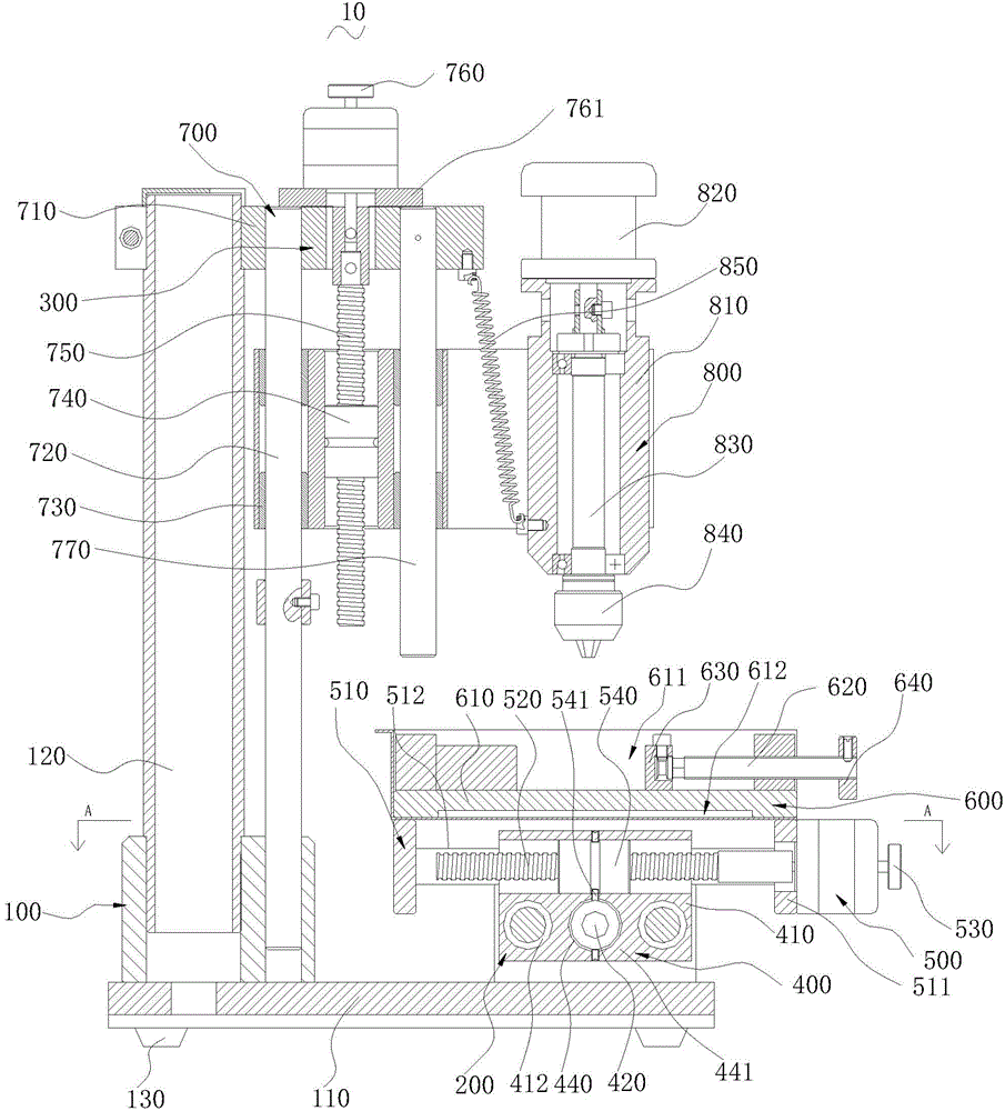
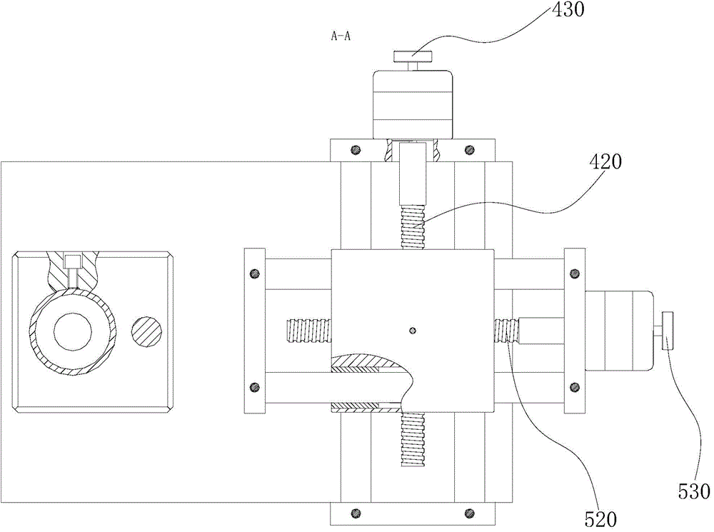
A punching machine comprises a base, a displacement device and a punching device. The displacement device comprises a Y-axis displacement mechanism, an X-axis displacement mechanism and a material placing piece. The Y-axis displacement mechanism comprises a Y-axis support, a Y-axis lead screw, a Y-axis adjusting rotating knob and a Y-axis screwing piece. The X-axis displacement mechanism comprises an X-axis support, an X-axis lead screw, an X-axis adjusting rotating knob and an X-axis screwing piece. The punching device comprises a Z-axis displacement mechanism and a punching mechanism connected with the Z-axis displacement mechanism. The Z-axis displacement mechanism comprises a Z-axis support, a Z-axis guiding column, a Z-axis lifting table, a Z-axis screwing piece, a Z-axis lead screw and a Z-axis adjusting rotating knob. The punching mechanism comprises a punching shaft sleeve, a punching air cylinder, a punching shaft and a punching head. According to the punching machine, by matching of the Y-axis displacement mechanism, the X-axis displacement mechanism and the Z-axis displacement mechanism, the punching mechanism can be driven to move in three freedom degrees, and accordingly a plurality of punching holes which are distributed irregularly can be punched by the punching machine.

Description

technical field [0001] The invention relates to the field of punching and forging, in particular to a punching machine. Background technique [0002] Stamping is a commonly used processing technology in the processing of metal sheets, relying on punches (or presses) and molds to exert external force on the sheet-like strips to cause plastic deformation or separation of the strips, thereby obtaining stamped parts of the required shape and size . Stamping includes two kinds of deformation process and separation process. The separation process is also called blanking. Its purpose is to separate the stamped parts from the strip along a certain contour line, while ensuring the quality requirements of the separation section. The purpose of the forming process is to make the strip plastically deform without breaking the billet to make a blank of the required shape and size. The blank is then subjected to subsequent grinding, polishing and other processes to make a stamped part of ...

Claims


Application Information

Patent Timeline
IPC IPC(8): B21D28/26B30B1/18B30B15/00
CPCB21D28/26B21D43/13B30B1/38B30B15/00
Inventor 张晶
Owner 河北林腾电力设备有限公司
Why Eureka
Try Eureka