Steel pipe clamp

A clamp and steel pipe technology, which is applied in the field of clamping equipment, can solve the problems of large, inconvenient clamping of small diameter steel pipes, and inconvenient operation.

Inactive Publication Date: 2015-03-25
CHONGQING THRIVE CHEM
View PDF8 Cites 5 Cited by
  • Summary
  • Abstract
  • Description
  • Claims
  • Application Information

AI Technical Summary

Problems solved by technology

Its shortcoming is that, when clamping with eccentric wheel, for steel pipes with different wall thickness, it is necessary to add a height adjustment gasket under the jaw, which is inconvenient to operate; due to the error of steel pipe wall thickness, the clamping is not reliable enough
[0004] Adopting the structure described in Chinese patent CN201046485, the overall structure of the hydraulic cylinder and piston rod is relatively complicated and bulky, and it is not convenient for the operator to clamp the steel pipe with a small diameter

Method used


Image

  • Steel pipe clamp

Examples


Embodiment Construction

[0020] The present invention will be described in further detail below by means of specific embodiments:

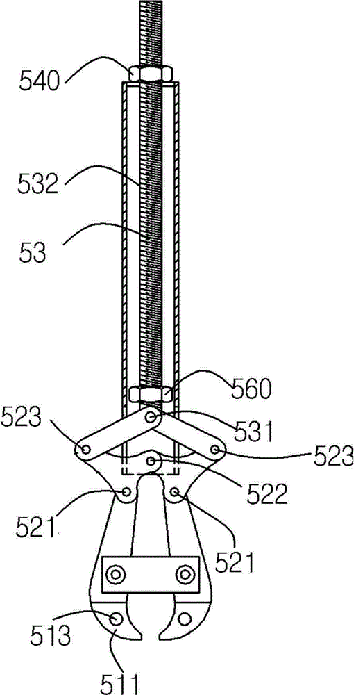
[0021] The reference signs in the drawings of the description include: the first nut 540, the threaded rod 53, the thread 532, the second nut 560, the rear hinge point 531, the middle hinge point 523, the front hinge point 522, the front end 521 of the front rod, the hanging ring 513 . The bending part 511 .

[0022] Such as figure 1 As shown, the steel pipe clamp of the present invention includes a sleeve, the front of the sleeve is provided with two opening slots opposite to each other, and the rear end of the sleeve is provided with an opening. The sleeve is made of No. 20 hot-rolled seamless steel pipe.

[0023] The sleeve is provided with a threaded rod 53, the threaded rod 53 is provided with a first nut 540 and a second nut 560, the threaded rod 53 passes through the hole into the sleeve, and is locked in by the first nut 540 The rear end of the sleeve and the f...


PUM


Abstract

The invention relates to clamping equipment of machinery in chemical industry, in particular to a steel pipe clamp. The steel pipe clamp comprises a sleeve and a four-connecting-rod mechanism, a first nut is arranged on a threaded rod which is arranged in the sleeve, the threaded rod penetrates out of the rear end of the sleeve and is locked at the rear end of the sleeve through the first nut, the four-connecting-rod mechanism penetrates into the front of the sleeve through an open slot and comprises a rear hinge joint point, two middle hinge joint points and a front hinge joint point, a clamp body with a bent portion is arranged at each of the front ends of two front rods, and the bent potions of the two clamp bodies are opposite. The steel pipe clamp has the advantages that the defects of complexity in mechanism and inconvenience in manual operation in the prior art are overcome, and the steel pipe clamp is adjustable in caliber and convenient for manual operation and is used for clamping small-diameter steel pipes.

Description

technical field [0001] The invention relates to a clamping device for chemical industrial machinery, in particular to a steel pipe clamp. Background technique [0002] When the steel pipe expanding machine carries out the overall diameter expansion of the steel pipe, it is necessary to rotate the weld seam of the steel pipe to the top and clamp it with the steel pipe clamp to make the steel pipe feed or retreat. Steel pipe clamps on foreign steel pipe expanding machines mostly use hydraulic cylinders and eccentric wheel mechanisms. Its shortcoming is that, to clamp steel pipes with different wall thicknesses with eccentric wheels, height adjustment gaskets need to be added under the jaws, which is inconvenient to operate; the clamping is not reliable enough due to the error of the steel pipe wall thickness. [0003] For this reason, Chinese patent CN201046485 discloses a steel pipe clamp. There are two lug plates on the front of the clamp seat. The lug plate flange mounting...

Claims


Application Information

Patent Timeline
IPC IPC(8): B21D43/00B21D39/08
CPCB21D43/003B21D39/08B21D43/10
Inventor 赵华文
Owner CHONGQING THRIVE CHEM
Why Eureka
Try Eureka