Supercharge Your Innovation With Domain-Expert AI Agents!

Broach for heat exchanging tube

A heat exchange tube and broach technology, applied in broach, broach, broach devices, etc., can solve the problems of poor cutting uniformity and low cutting efficiency, achieve good cutting uniformity, improve cutting efficiency, and facilitate setting and viewing Effect

Inactive Publication Date: 2015-03-25
HUANYA TIANJIN MARINE HEAT EXCHANGER
View PDF0 Cites 0 Cited by
  • Summary
  • Abstract
  • Description
  • Claims
  • Application Information

AI Technical Summary

Problems solved by technology

However, the broach with this structure has the problems of poor cutting uniformity and low cutting efficiency in actual use.

Method used


Image

  • Broach for heat exchanging tube
  • Broach for heat exchanging tube

Examples


Embodiment

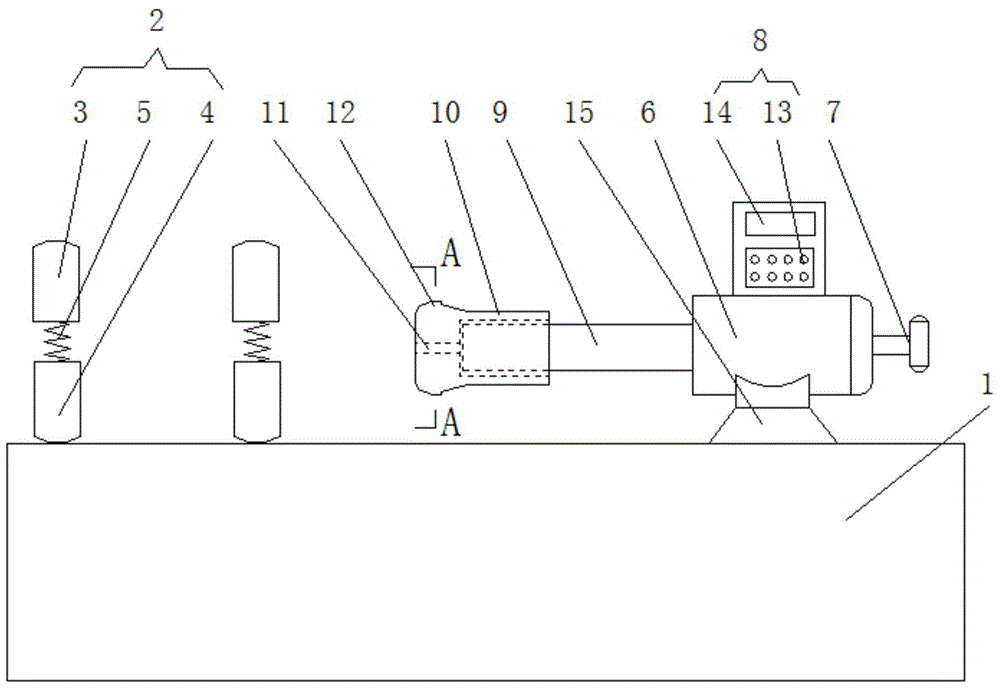
[0020] Such as Figure 1-Figure 2 As shown, this embodiment includes a processing table 1, a pipe clamp 2, an upper half ring 3, a lower half ring 4, a spring 5, a linear motor 6, a rotary handle 7, a positioning device 8, a telescopic push rod 9, a cutter body 10, and a channel 11 and cutter head 12, pipe clamp 2 is installed on the upper left part of processing table 1, pipe clamp 2 includes upper half ring 3, lower half ring 4 and spring 5, lower half ring 4 is fixed on the processing table 1, lower half ring The two sides of 4 are connected to the upper half ring 3 through the spring 5. There are two pipe clamps 2. The distance between the pipe clamps 2 is consistent with the length of the telescopic push rod 9. The upper right part of the processing table 1 is fixed. There is a linear motor 6, a rotating handle 7 is installed in the middle part of the rear side of the linear motor 6, a positioning device 8 is arranged on the upper side of the linear motor 6, and the posit...


PUM


Abstract

The invention belongs to the technical field of broach equipment, and particularly relates to a broach for a heat exchanging tube. The broach comprises a machining table, a tube clamp, an upper half ring, a lower half ring, springs, a linear motor, a rotating handle, a positioning device, a flexible push rod, a broach body, a channel and a broach head, wherein the tube clamp is arranged on the left of the upper side of the machining table and comprises the upper half ring, the lower half ring and the springs; the lower half ring is fixed on the machining table; two sides of the lower half ring are correspondingly connected with the upper half ring through the springs; the linear motor is fixed on the right of the upper side of the machining table; the rotating handle is arranged in the middle of the rear side of the linear motor; the positioning device is arranged on the upper side of the linear motor; the flexible push rod is arranged in the middle of the front side of the linear motor; and the front of the flexible push rod is in threaded connection with the broach body. The broach for the heat exchanging tube is high in cutting uniformity and high in cutting efficiency.

Description

technical field [0001] The invention belongs to the technical field of broach equipment, in particular to a broach used for heat exchange tubes. Background technique [0002] At present, the broach is a forming tool used for broaching. When the inner heat exchange tube of the air cooler of the offshore motor breaks, the heat exchange medium will flow into the flow channel through the hydrophobic groove on the outer heat exchange tube, so a broach is required The pipe wall of the outer heat exchange tube is cut into water-repellent grooves. The broach in the prior art includes a broach main body, and a plurality of cutter teeth are arranged on the broach main body, and a chip container is arranged between two adjacent cutter teeth. Groove, the main cutting edge of the cutter teeth is concave along the broaching direction, the broach body also includes a broaching base plate, a plurality of cutter teeth are arranged in one or more rows on the broaching base plate, and the broa...

Claims


Application Information

Patent Timeline
Patent Type & Authority Applications(China)
IPC IPC(8): B23D41/00B23D41/06B23D41/08B23D43/02
Inventor 孔宪龙施剑南杨杰
Owner HUANYA TIANJIN MARINE HEAT EXCHANGER
Features
  • R&D
  • Intellectual Property
  • Life Sciences
  • Materials
  • Tech Scout
  • Unparalleled Data Quality
  • Higher Quality Content
  • 60% Fewer Hallucinations
Learn More