
Cutting device in use for line of cooling film

A cooling line, film technology, applied in applications, household appliances, other household appliances, etc., can solve the problems of uneven cutting, continuous film cutting, low cutting efficiency, etc., to achieve compact and simple structure, straight and accurate incision, The effect of accurate and stable position

Inactive Publication Date: 2008-12-24
LARSEN&TOUBRO QINGDAO RUBBER MACHINERY
View PDF8 Cites 0 Cited by
  • Summary
  • Abstract
  • Description
  • Claims
  • Application Information

AI Technical Summary

Problems solved by technology

These two cutting technology methods have disadvantages such as low cutting efficiency, sometimes the film is cut continuously, and the cutting is uneven.

Method used


Image

  • Cutting device in use for line of cooling film

Examples


Embodiment Construction

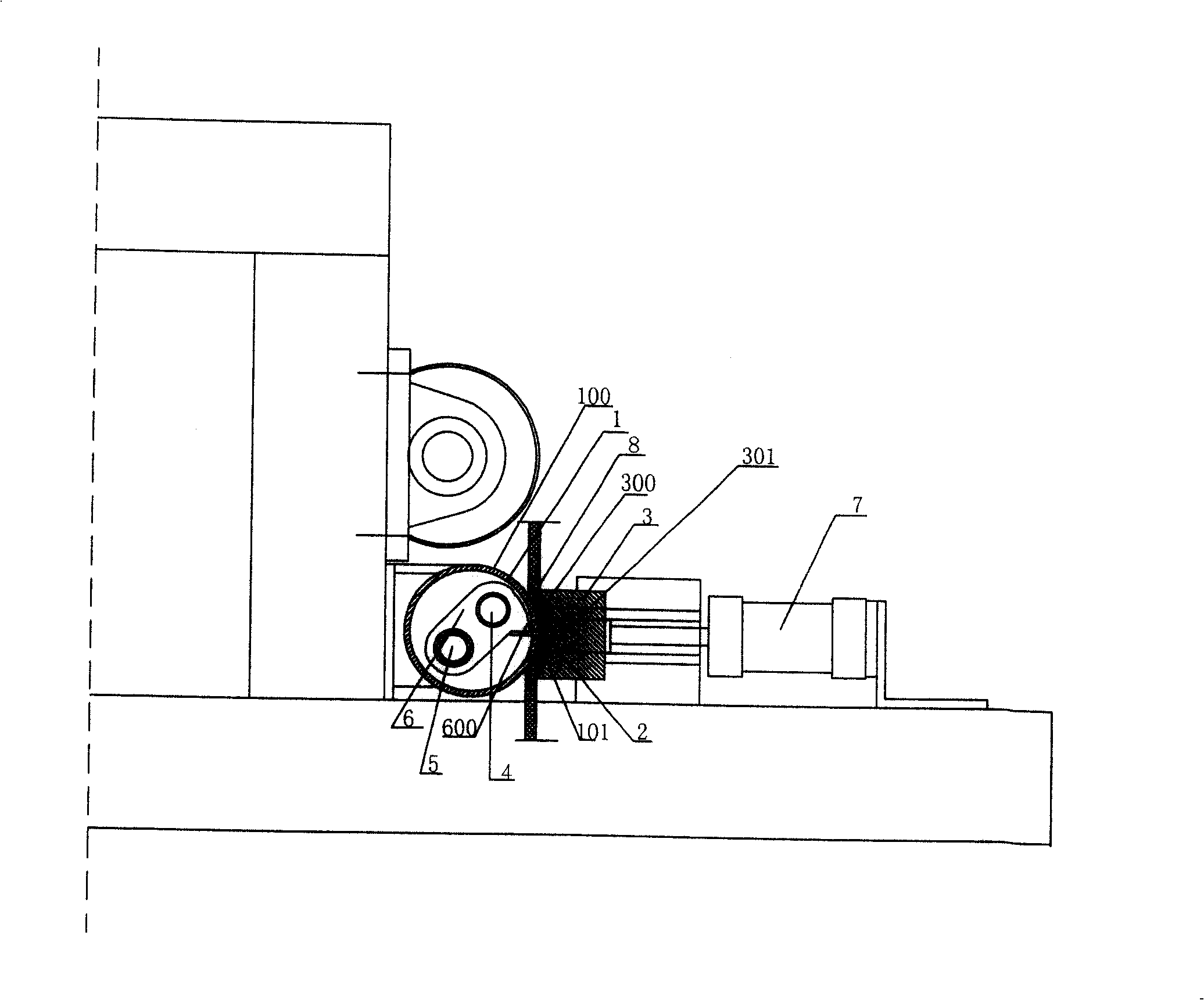
[0015] Combined with the figure, a cutting device for film cooling line, the static support part 1 of the film clamping mechanism is cylindrical, the cylinder wall is provided with a cutting knife notch 101 extending along the length direction, the dynamic pressure of the film clamping mechanism The part 3 is plate-shaped, and the dynamic pressure part 3 is equipped with a direct-acting push-pull device 7, which can be an air cylinder or a hydraulic oil cylinder, and its pressing surface 300 is an arc-shaped surface suitable for the outer cylinder wall 100 of the static support part. On the side of the pressing surface of the dynamic pressure part 3, there is a cutter head receiving notch 301 extending along the length direction directly opposite to the position of the cutter notch, and the dynamic pressure part 3 can be driven by the action of the straight-moving push-pull device 7. The pressure part 3 presses the film to be cut to the direction of the static support part 1 an...


PUM


Abstract

The invention discloses a cutting device for a film cooling line, which comprises a film clamping mechanism and a cutter cutting mechanism; Between the dynamic pressure part and the static support part; the above-mentioned cutter cutting mechanism is provided with a cutter and a slider that drives the cutter to slide back and forth, the above-mentioned cutter is provided with a side edge, and the slider can drive the cutter to make the side edge The outer edge of one side of the quasi-cut part of the film to be cut passes through the sheet body and crosses the outer edge of the other side to form an incision where the cut piece is separated from the film. Compared with the prior art, it has the advantages of straight and accurate incision, good uniformity of cutting pieces, high cutting efficiency and the like.

Description

technical field [0001] The invention relates to a film cooling line in the production of all-steel truck radial tires, bias rubber tires, etc., and is particularly related to a cutting device used for cutting cooling film in the film cooling line. Background technique [0002] In the prior art, the film cooling line in the production of all-steel radial truck tires and bias rubber tires adopts two methods for cooling film cutting, one is manual cutting, and the other is formed by a rodless cylinder driving a cutting knife. Cutting device for cutting pieces. These two kinds of cutting techniques have the disadvantages of low cutting efficiency, continuous cutting of film sometimes, and uneven cutting. Contents of the invention [0003] The task of the present invention is to solve the disadvantages of uneven cutting and low cutting efficiency in the prior art film cutting methods or devices, and provide a new cutting device for film cooling lines. [0004] Its technical s...

Claims


Application Information

Patent Timeline
Patent Type & Authority Patents(China)
IPC IPC(8): B26D1/11B26D7/01B29D30/08
Inventor 管阳春殷晓于云港
Owner LARSEN&TOUBRO QINGDAO RUBBER MACHINERY
Learn More