Special clamp for multi-directionally clamping frame workpieces

A special fixture and frame technology, applied in the direction of manufacturing tools, metal processing machinery parts, clamping and other directions, can solve the problems of affecting the machining accuracy, the pressure loss of the frame workpiece, and the low qualified rate of the finished product, so as to avoid movement and improve processing. The effect of precision, simple structure

Active Publication Date: 2015-03-25
FOSHAN PRATIC CNC SCI & TECH
View PDF5 Cites 8 Cited by
  • Summary
  • Abstract
  • Description
  • Claims
  • Application Information

AI Technical Summary

Problems solved by technology

In the processing of LCD TV frame workpieces, the frame workpieces are generally clamped by double fixed clamping fixtures on the left and right sides of the cylinder. When the workpiece is processed, it only receives the radial clamping force in the Y direction, and the workpiece in the Z direction axis It is easy to move and affect the precision of processing
In addition, because the clamping contact surface of the frame workpiece is small, if the radial clamping force is increased, the pressure loss of the frame workpiece may occur, so that the processing of the frame workpiece is not precise, and the qualified rate of the finished product is not high

Method used


Image

  • Special clamp for multi-directionally clamping frame workpieces
  • Special clamp for multi-directionally clamping frame workpieces
  • Special clamp for multi-directionally clamping frame workpieces

Examples


Embodiment Construction

[0026] The technical solutions of the present invention will be further described below in conjunction with the accompanying drawings and through specific implementation methods.

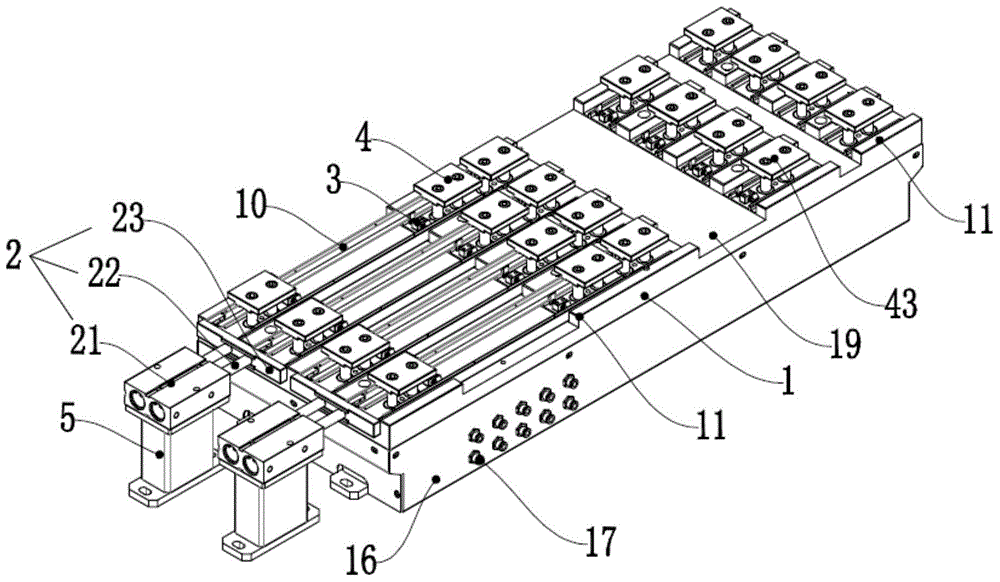
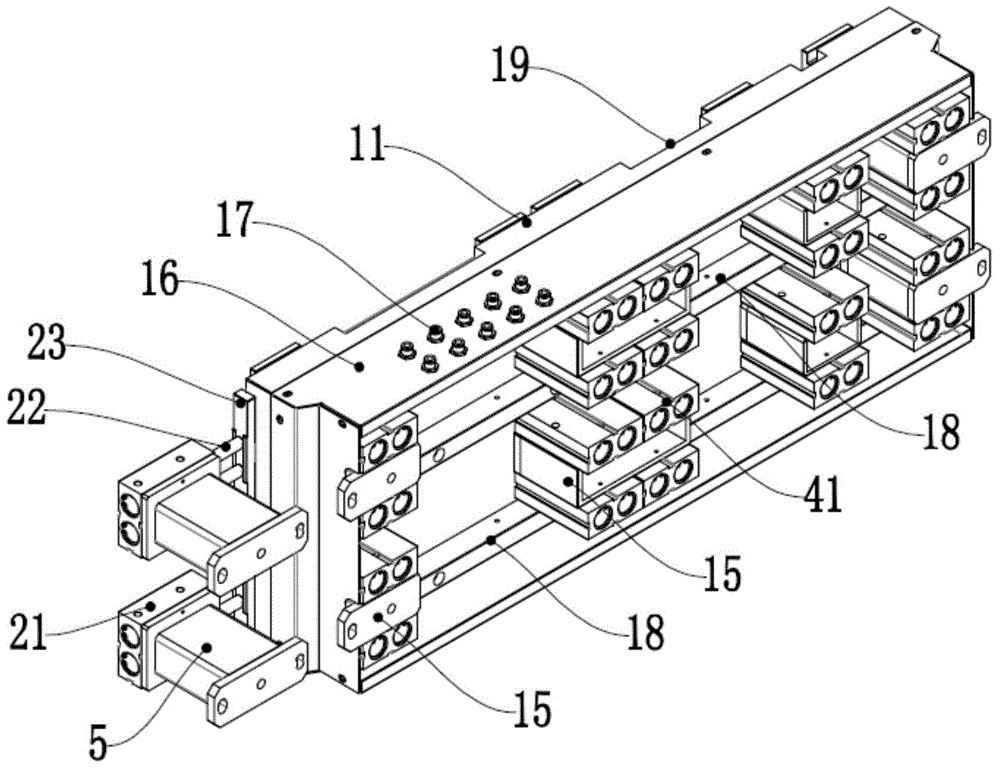
[0027] A special fixture for multi-directional clamping of frame workpieces, including a base plate 1, multiple Y-direction automatic positioning devices 3 and multiple Z-direction positioning devices 4;

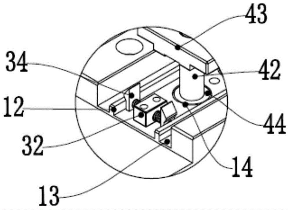
[0028] A row or more than one row of segmented clamping grooves 11 is horizontally arranged on the working table of the base plate 1, and the frame workpieces 10 are respectively placed on both sides of the grooves in the lateral direction of the clamping grooves 11. , the groove bottom surface of the clamping groove 11 is provided with a plurality of slot holes 14 for installing the positioning device along the position of the transverse centerline in the groove;

[0029] The Y-direction positioning device 3 is arranged on the groove surface of the clamping groove 11 through the slot hole 14, and...


PUM


Abstract

The invention relates to a special clamp for multi-directionally clamping frame workpieces. The special clamp comprises a baseplate, a plurality of Y-direction automatic positioning devices and a plurality of Z-direction positioning devices, wherein a row or more rows of sectional type clamping slots are transversely formed in the working table of the baseplate; the Y-direction positioning devices are arranged on the slot surfaces of the clamping slots through slot holes, and the Y-direction automatic positioning devices provide positioning thrust perpendicular to transverse center lines on two edges for the frame workpieces on the two edges to carry out Y-direction positioning on the frame workpieces; the Z-direction positioning devices are vertically mounted in the clamping slots through slot holes, and provide positioning pressure perpendicular to the baseplate for the rame workpieces at the two edges to carry out Z-direction positioning for the frame workpieces. The special clamp has a perpendicular clamping positioning function and avoids of axial play of the workpieces during processing. The special clamp has the advantages of being reasonable in structure and attractive and neat in appearance.

Description

technical field [0001] The invention relates to the field of machining fixtures, in particular to a special fixture for multi-directional clamping of frame workpieces. Background technique [0002] With the development of numerical control technology, many parts of products are processed by CNC machine tools. Generally, fixtures need to be installed on the machine tool to clamp the workpiece or guide the tool. Its function is to position the workpiece so that the workpiece can obtain relative The correct position, and reliable clamping of the workpiece. In the processing of LCD TV frame workpieces, the frame workpieces are generally clamped by double fixed clamping fixtures on the left and right sides of the cylinder. When the workpiece is processed, it only receives the radial clamping force in the Y direction, and the workpiece in the Z direction axis It is prone to movement and affects the accuracy of processing. In addition, because the clamping contact surface of the ...

Claims


Application Information

Patent Timeline
Patent Type & Authority Applications(China)
IPC IPC(8): B23Q3/08B23Q11/08
CPCB23Q3/062B23Q3/08B23Q11/08B23Q2703/04
Inventor 刘世泉马继罗家海赵小雨
Owner FOSHAN PRATIC CNC SCI & TECH
Why Eureka
Try Eureka