
Thermal shield tool clamp

A technology of tooling fixtures and heat shields, which is applied in the direction of manufacturing tools and workpiece clamping devices, can solve problems such as complex structure of heat shield positioning tooling, hidden dangers of personal safety of operators, and inability to ensure assembly accuracy, etc., to achieve simple structure, The effect of low cost and easy replacement

Active Publication Date: 2015-03-25
LIUZHOU YINGHANG AUTO PARTS
View PDF4 Cites 1 Cited by
  • Summary
  • Abstract
  • Description
  • Claims
  • Application Information

AI Technical Summary

Problems solved by technology

[0002] When assembling the automobile heat shield, a positioning tool is required. However, the existing heat shield positioning tool has a complex structure and high cost, and is only suitable for some large automobile factories. For small automobile factories, a simple Position the tooling structure, so that the assembly accuracy cannot be guaranteed during assembly, and at the same time, it brings great hidden dangers to the personal safety of operators

Method used


Image

  • Thermal shield tool clamp
  • Thermal shield tool clamp

Examples


Embodiment Construction

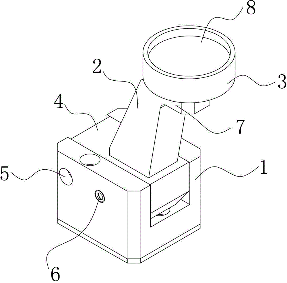
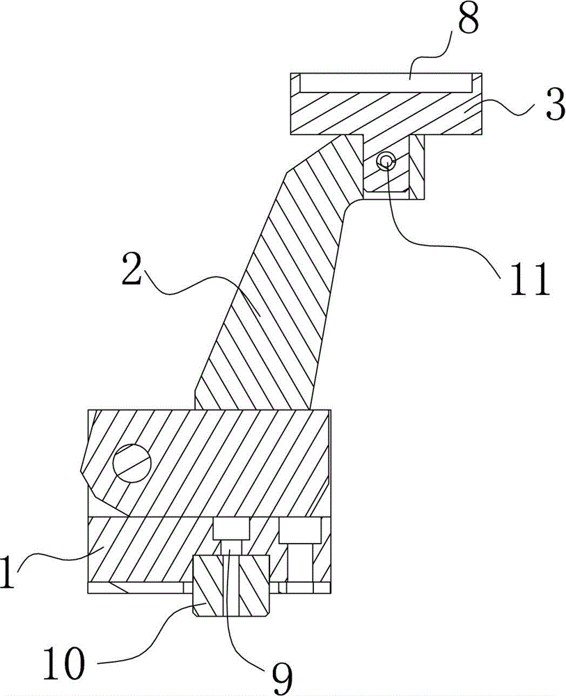
[0012] Such as Figure 1-2 As shown, a heat shield fixture described in the embodiment of the present invention mainly includes a base 1, a bracket 2 and a support block 3, the base 1 is a square body, a square groove is arranged in the middle of the base 1, and one end of the bracket 2 It is the socket block 4, and the socket block 4 is plugged in the square groove. A spring pin 6 and a rotating shaft 5 are arranged at the joint between the socket block 4 and the base 1. There is an angle between the bracket 2 and the top surface of the base 1. In the bracket The top end of 2 is provided with a horizontal extension 7, one end of the support block 3 is inserted into the horizontal extension 7 and fixed by a positioning pin 11, the other end of the support block 3 is disc-shaped, and the top of the support block 3 is provided with a depression 8, A countersunk hole is arranged in the square groove, and the base 1 is connected with a positioning post 10 through a screw 9 .

[0...


PUM


Abstract

The invention discloses a thermal shield tool clamp which mainly comprises a base, a support and a supporting block. The base is a cuboid, a square groove is formed in the middle of the base, an insertion block is arranged at one end of the support and inserted in the square groove, a spring pin and a rotary shaft are arranged at the matching portion of the insertion block and the base, the included angle is formed between the support and the top face of the base, a horizontal extending part is arranged at the top end of the support, one end of the supporting block is inserted in the horizontal extending part and is fixed through a locating pin, the other end of the supporting block is a disc, a recessed part is arranged at the top end of the supporting block, a counterbored hole is formed in the square groove, and the base is connected with a locating column through a screw. According to the thermal shield tool clamp, a thermal shield is located through the supporting block, the tool requirements of the thermal shield are met, the base and the locating column are connected, the locating function can be achieved when the base is connected with a bottom board on the bottom face, the use performance of the tool clamp is improved, and personal safety of operators can be guaranteed.

Description

technical field [0001] The invention relates to the field of automobile positioning tooling, in particular to a heat shield tooling fixture. Background technique [0002] When assembling the automobile heat shield, a positioning tool is required. However, the existing heat shield positioning tool has a complex structure and high cost, and is only suitable for some large automobile factories. For small automobile factories, a simple Position the tooling structure, so that the assembly accuracy cannot be guaranteed during assembly, and at the same time, it brings great hidden dangers to the personal safety of the operators. Contents of the invention [0003] In order to solve the above-mentioned technical problems, the present invention provides a fixture for a heat shield. The positioning fixture has a simple structure and low cost, which can ensure assembly accuracy and ensure the personal safety of operators. [0004] The purpose of the present invention is specifically ...

Claims


Application Information

Patent Timeline
IPC IPC(8): B25B11/02
CPCB25B11/02
Inventor 莫海燕
Owner LIUZHOU YINGHANG AUTO PARTS
Learn More