
Frameless composite heat-insulation fireproof glass splicing structure

A fireproof glass and fireproof glue layer technology, which is applied to glass/slag layered products, building components, building structures, etc. Aesthetics, strength and safety, flame and temperature resistance

Inactive Publication Date: 2015-03-25
余永翀
View PDF0 Cites 3 Cited by
  • Summary
  • Abstract
  • Description
  • Claims
  • Application Information

AI Technical Summary

Problems solved by technology

[0002] At present, all composite heat-insulating fire-resistant glass must be inlaid in a thick heat-insulating frame, and composite heat-insulating fire-resistant glass with a larger area must also be separated by a frame. The frame between the glass seriously affects the transparent effect of the glass. Moreover, the heat insulation effect and strength of the frame will also affect the overall fire resistance effect.

Method used


Image

  • Frameless composite heat-insulation fireproof glass splicing structure
  • Frameless composite heat-insulation fireproof glass splicing structure
  • Frameless composite heat-insulation fireproof glass splicing structure

Examples


Embodiment 1

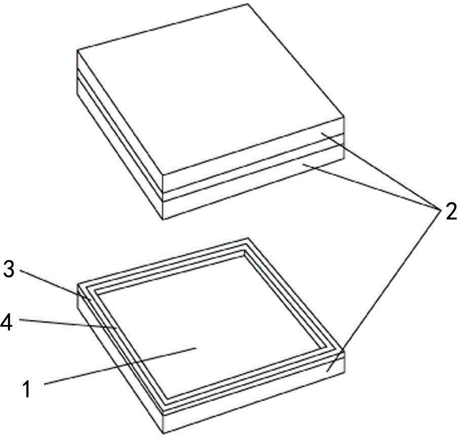
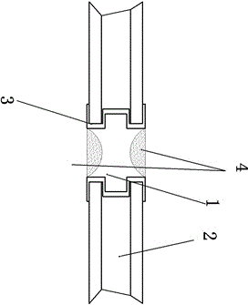
[0018] see Figure 1-2 As shown, the present invention relates to a frameless composite heat-insulating fireproof glass splicing structure, which includes two pieces of fireproof glass substrates 2, and the fireproof glass substrates 2 are arranged in parallel with each other. There is a PVC bead 3, and the heat-insulating bead 3 and the adjacent fireproof glass substrate 2 form a sealed accommodation chamber, and two layers of silicone rubber layer 4 and a layer of transparent fireproof glue layer 1 are poured into the chamber, so that The above-mentioned transparent fireproof adhesive layer 1 is arranged between two silicone adhesive layers 4 .

[0019] A method for manufacturing a frameless composite heat-insulating fireproof glass splicing structure, the steps comprising:

[0020] (1) First set and fix the two fire-resistant glass substrates in parallel up and down to make the facade smooth;

[0021] (2) Adjust the distance between the two fire-resistant glass substrates...

Embodiment 2

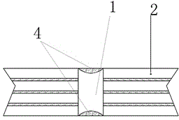
[0026] see figure 1 and 3 As shown, the present invention relates to a frameless composite heat-insulating fireproof glass splicing structure, including four pieces of fireproof glass substrates 2, the fireproof glass substrates 2 are arranged parallel to each other, and the gaps between each adjacent fireproof glass substrates form a container Two layers of silicone rubber layers 4 are poured on both sides of the cavity, and a layer of transparent fireproof glue layer 1 is poured in the middle, and the transparent fireproof glue layer 1 is arranged between the two silicone rubber layers 4 .

[0027] A method for manufacturing a frameless composite heat-insulating fireproof glass splicing structure, the steps comprising:

[0028] (1) First set and fix the two fire-resistant glass substrates in parallel up and down to make the facade smooth;

[0029] (2) Adjust the distance between the two fire-resistant glass substrates as small as possible, and form an accommodation cavity ...


PUM


Abstract

The invention relates to the field of fireproof glass and particularly relates to a frameless composite heat-insulation fireproof glass splicing structure. The frameless composite heat-insulation fireproof glass splicing structure has the advantages of good fireproof and heat-insulation performances of fireproof glass, omitting of a framework structure and enhancement of transparent beautiful effect of the fireproof glass. The frameless composite heat-insulation fireproof glass splicing structure comprises at least two pieces of fireproof glass substrates; the fireproof glass substrates are arranged in parallel; a heat-insulation pressing strip is arranged between the adjacent edges of each fireproof glass substrate; a sealed containing cavity is formed by each heat-insulation pressing strip and the adjacent fireproof glass substrate, and is filled with at least two sealing glue layers and at least one transparent fireproof glue layer; and the transparent fireproof glue layer is arranged between the two sealing glue layers.

Description

technical field [0001] The invention relates to the field of fire-resistant glass, in particular to a frameless composite heat-insulating fire-proof glass splicing structure which has good fire-resistant and heat-insulating performance of the fire-resistant glass, and can remove the frame structure and increase the transparent and beautiful effect of the fire-resistant glass. Background technique [0002] At present, all composite heat-insulating fire-resistant glass must be inlaid in a thick heat-insulating frame, and composite heat-insulating fire-resistant glass with a larger area must also be separated by a frame. The frame between the glass seriously affects the transparent effect of the glass. Moreover, the heat insulation effect and strength of the frame will also affect the overall fire resistance effect. Contents of the invention [0003] In order to solve the above problems, the present invention provides a frameless composite heat-insulating fire-proof glass sp...

Claims


Application Information

Patent Timeline
Patent Type & Authority Applications(China)
IPC IPC(8): B32B17/06B32B7/12B32B3/08
CPCE04B1/948E04B1/942E04C2/54E04C2/543
Inventor 余永翀
Owner 余永翀
Learn More