Eureka AIR delivers breakthrough ideas for toughest innovation challenges, trusted by R&D personnel around the world.

Special hydraulic transfer trolley for power distribution cabinet

A hydraulic type and power distribution cabinet technology, which is applied to trolleys, motor vehicles, multi-axis trolleys, etc., can solve the problems of unsatisfactory adjustment height range, slow adjustment speed, and inconvenient operation, so as to improve work efficiency and safety, and operate relaxing effect

Inactive Publication Date: 2015-03-25
江苏金华厦电气有限公司
View PDF7 Cites 8 Cited by
  • Summary
  • Abstract
  • Description
  • Claims
  • Application Information

AI Technical Summary

Problems solved by technology

In this case, work efficiency and safety issues will not be guaranteed
[0004]2. The operation is inconvenient, and the height adjustment is inconvenient during the docking process with the switch cabinet
The height of the transfer vehicle needs to be adjusted during the process of docking with the switchgear. The conventional transfer vehicle is realized by adjusting the nylon handwheels on the four load-bearing bolts respectively. This way of adjustment is slow, and sometimes due to the uneven operation plane The reason is that the transfer vehicle needs to be adjusted to a large extent and the adjustment height range of the transfer vehicle cannot meet the requirements of sending the circuit breaker from the transfer vehicle into the handcart room.

Method used


Image

  • Special hydraulic transfer trolley for power distribution cabinet
  • Special hydraulic transfer trolley for power distribution cabinet
  • Special hydraulic transfer trolley for power distribution cabinet

Examples


Embodiment Construction

[0013] The present invention will be further described below in conjunction with the accompanying drawings.

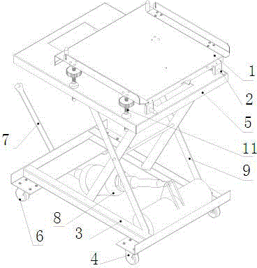
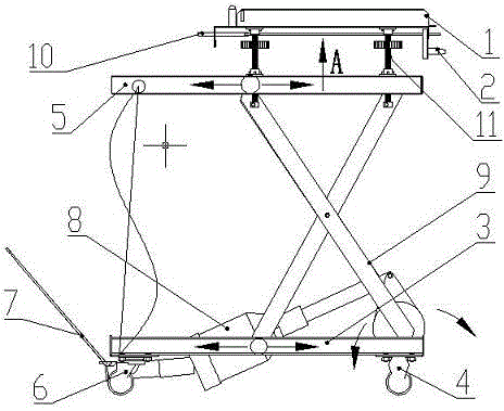
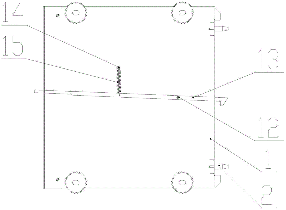
[0014] As shown in the figure, the special hydraulic transfer vehicle for power distribution cabinets of the present invention includes a positioning plate 1 and a lifting bracket. The positioning plate is connected to the lifting bracket through four adjusting bolts 11 at the bottom of the positioning plate. The lifting bracket can greatly adjust the power distribution cabinet. After the height of the special hydraulic transfer vehicle, adjust the bolt 11 to further fine-tune the height of the four corners of the positioning plate to ensure that the large accessories of the electrical cabinet such as circuit breakers are smoothly pushed into the guide rails of the electrical cabinet.

[0015] The lifting support includes an upper frame 5 with guide rails, a lower frame 3, legs 9 and a hydraulic jack 8, one end of the hydraulic jack is connected to the lower frame 3, an...


PUM


Abstract

The invention relates to a special hydraulic transfer trolley for a power distribution cabinet, and belongs to the technical field of electric cabinet assembly. The special hydraulic transfer trolley for the power distribution cabinet comprises a lifting support. The lifting support comprises an upper frame, a lower frame, supporting legs and a hydraulic jack, wherein the upper frame and the lower frame are provided with guide rails. One end of the hydraulic jack is connected to the lower frame, the other end of the hydraulic jack is connected to the supporting legs, and stretching and contracting of the hydraulic jack drive one ends of the supporting legs to swing along the connecting points between the supporting legs and the frames and the other ends of the supporting legs to slide along the guide rails of the frames. According to the special hydraulic transfer trolley for the power distribution cabinet, the size of the angle of the lifting support is adjusted through the hydraulic jack to enable the special hydraulic transfer trolley for the power distribution cabinet to rise or fall, when the special hydraulic transfer trolley for the power distribution cabinet is adjusted to be at the lowest height, electrical cabinet large accessories such as a circuit breaker can be carried onto the special hydraulic transfer trolley for the power distribution cabinet very easily, in this way, operation is easy and convenient, and the effect of greatly improving working efficiency and safety is achieved.

Description

technical field [0001] The invention belongs to the technical field of electric cabinet assembly, and in particular relates to a special hydraulic transfer vehicle for power distribution cabinets for safely carrying large accessories of electric cabinets. Background technique [0002] The conventional transfer vehicle has been widely used by manufacturers due to its simple structure, convenient processing and low cost, but it has the following defects: [0003] 1. It is not safe, and the large accessories of electrical cabinets such as circuit breakers are transported from the transfer vehicle to the ground (the ground is transported to the transfer vehicle) under normal circumstances by manpower or a hoist. Considering the conditions of the facilities on site, it is mainly carried by manpower. The height of a conventional transfer vehicle is about 0.8 meters, and the weight of a conventional circuit breaker is about 120-150 kg. In this case, work efficiency and safety is...

Claims


Application Information

Patent Timeline
Patent Type & Authority Applications(China)
IPC IPC(8): B62B3/02B66F7/08B66F7/28
Inventor 谭雪峰宋振达黄小聚刘正鹏
Owner 江苏金华厦电气有限公司
Why Eureka
Eureka Blog
Learn More