Wire winding disc and steel bar binding machine

A wire reel and wire reel technology, which is applied in construction, building construction, and building material processing, can solve the problems affecting the normal use of the machine, the beginning end of the steel wire is easy to enter the machine, and the beginning end of the steel wire is not fixed firmly. Saves maintenance and cleanup time, reduces likelihood, enhances fixation effects

Active Publication Date: 2015-03-25
TAIZHOU XINDALU ELECTRONICS TECH
View PDF7 Cites 5 Cited by
  • Summary
  • Abstract
  • Description
  • Claims
  • Application Information

AI Technical Summary

Problems solved by technology

The starting end of the steel wire in the above structure is not fixed firmly. When the steel wire is exhausted, the starting end of the steel wire is easy to enter the machine, which affects the normal use of the machine.

Method used


Image

  • Wire winding disc and steel bar binding machine
  • Wire winding disc and steel bar binding machine
  • Wire winding disc and steel bar binding machine

Examples


Embodiment 1

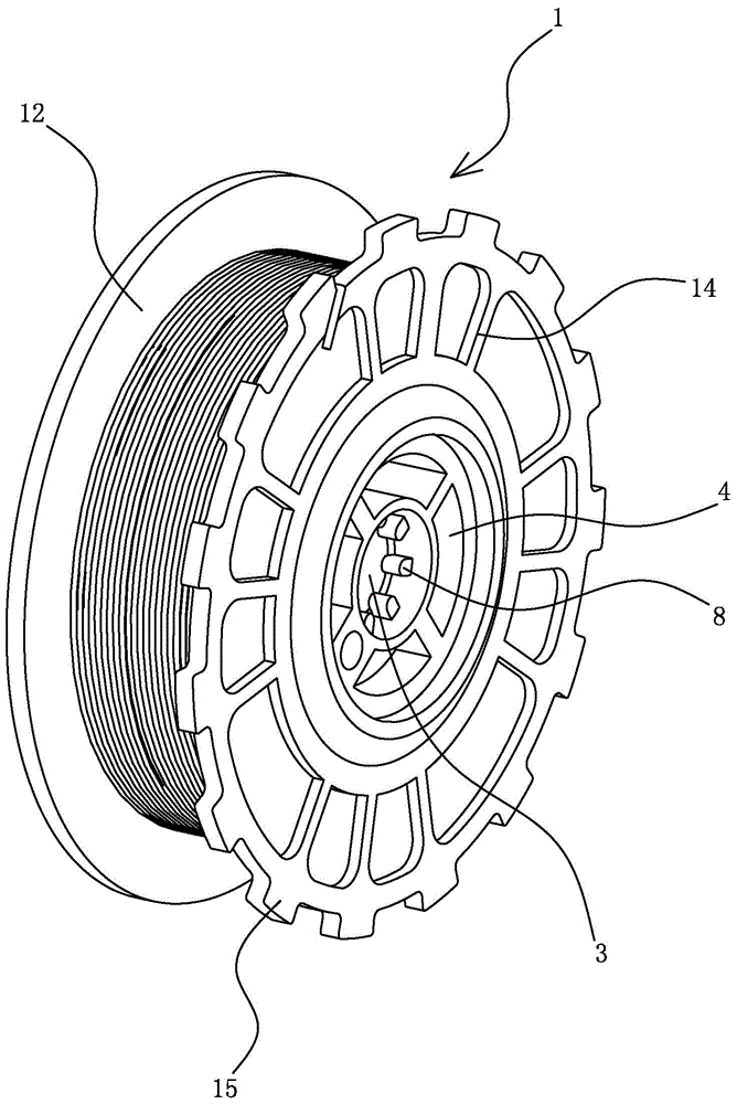
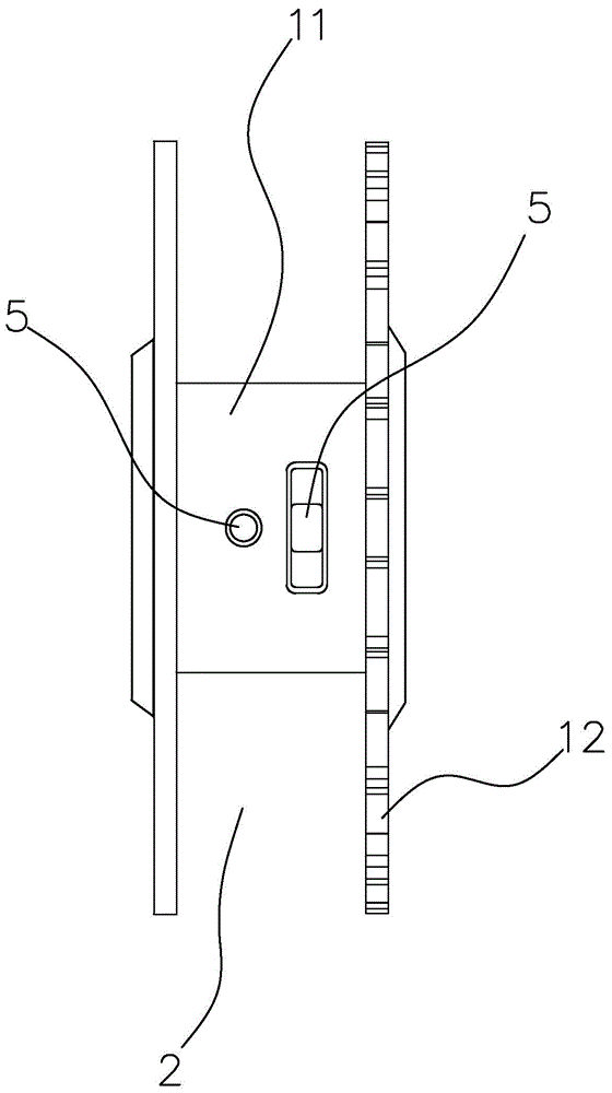
[0028] see Figure 1 to Figure 3 According to the winding reel provided by the present invention, the through hole 5 is provided as one, and the through hole 5 communicates with the annular structure 4 or the installation hole 3, and the through hole 5 of the present invention can also pass through The annular structure 4 communicates with the installation hole 3, and the present invention provides one through hole 5 on the shaft sleeve 11, the annular structure 4 is connected with the through hole 5, and the beginning end of the steel wire 6 passes through the through hole 5 and enters the Annulus structure 4, the end of steel wire 6 is knotted in annulus structure 4, and is wound into a multi-turn knot with a diameter larger than through hole 5, so that after the steel wire 6 on the wire coil is used up or not enough When performing the next bundling, the knotting part of the steel wire can be clamped on the through hole 5, effectively preventing the beginning end of the ste...

Embodiment 2

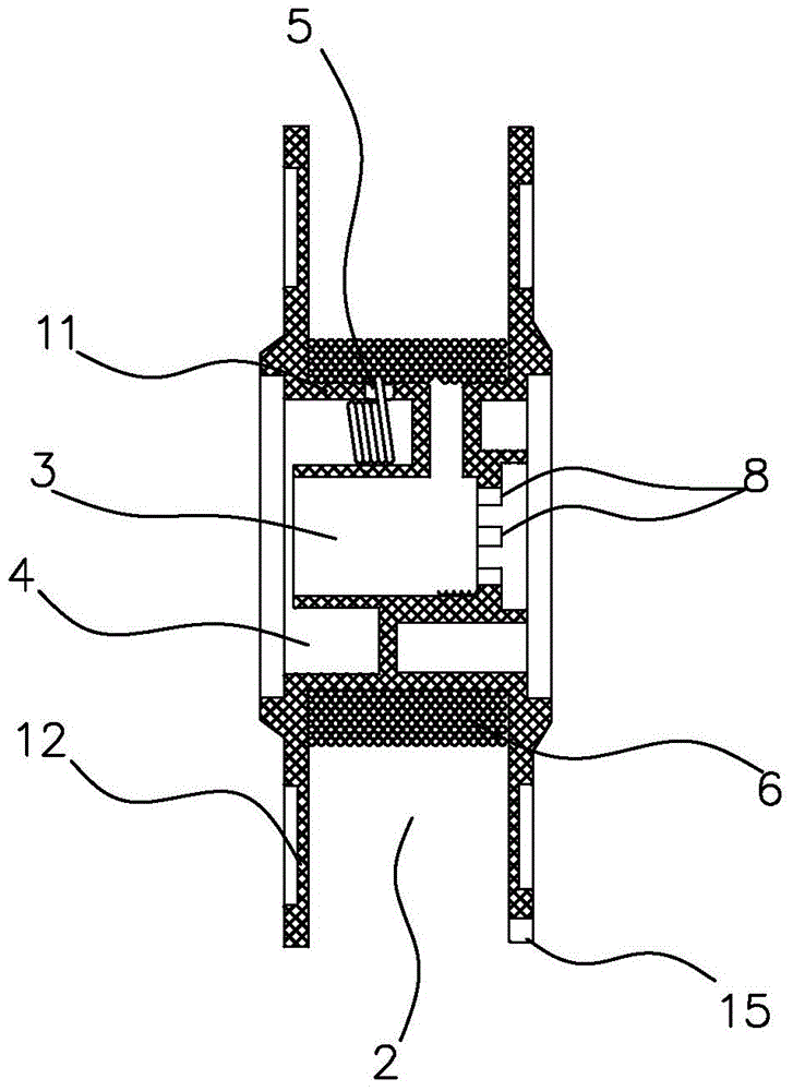
[0030] see Figure 1 to Figure 4 According to the wire reel provided by the present invention, the present invention also provides another embodiment of a through hole 5 opened on the shaft sleeve 11, the through hole 5 is communicated with the installation hole 3, and the beginning end of the steel wire 6 passes through the through hole 5. The hole 5 enters the installation hole 3, and is knotted at the middle position of the installation hole 3 to form a knot with a diameter larger than the diameter of the through hole 5. The above-mentioned middle position is located at the middle position of the two ends of the installation hole 3. When it is used up or not enough for the next binding, the end of the steel wire 6 can be clamped on the through hole 6, effectively preventing the beginning of the steel wire from falling off from the wire reel and entering the machine to affect the work of the machine itself Next, when the winding reel is installed on the binding machine or ot...

Embodiment 3

[0032] see Figure 1 to Figure 4 , according to the winding reel provided by the present invention, the present invention also provides a third embodiment of the through hole 5 provided on the sleeve 11, the through hole 5 is set to two, and the two through holes 5 are respectively connected with The annular structure 4 communicates with the installation hole 3, and the starting end of the steel wire 6 can pass through one of the through holes 5 to be knotted in the installation hole 3 or the annular structure 4 to form a knot with a diameter larger than the diameter of the through hole 5 part, also can first pass through one of the through holes 5 for knotting, then pass through another through hole 5 for secondary knotting to form a knotted part with a diameter greater than the diameter of the through hole 5, and the reinforcing steel wire 6 is about to be used up or It is not enough for the fixing effect of the next binding, which greatly reduces the possibility of the rema...


PUM


Abstract

The invention provides a wire winding disc. The wire winding disc comprises a wire winding disc body. The wire winding disc body is composed of a shaft sleeve and two side plates, wherein the shaft sleeve and the two side plates are integrally formed. A winding cavity for a steel wire is formed by the bottom wall of the shaft sleeve and the two side plates, an installation hole is formed in the center of the shaft sleeve, a through hole with the minimal diameter larger than the diameter of the steel wire is formed in the shaft sleeve, and the initial end of the steel wire penetrates through the through hole and then is knotted and fixed. The wire winding disc and a binding machine have the advantages that a round hole and the through hole are formed in the wire winding disc, the end of the steel wire is wound so that the diameter of the end can be larger than that of the round hole, the end of the steel wire can be fixed, the initial end of the steel wire is effectively prevented from not falling off the wire winding disc, and after the wire disc stops working, a last steel wire head cannot be pulled to the machine to affect work of a next disc.

Description

technical field [0001] The invention relates to a wire winding reel, and also relates to a binding machine equipped with the wire winding reel. Background technique [0002] The steel bar binding device has: a binding wire delivery mechanism that sends out a binding wire such as a steel wire wound on a reel and winds it around a steel bar; and a binding wire twisting mechanism that twists the binding wire wound around a steel bar, Through the operation of the starter, the binding wire sending mechanism and the binding wire twisting mechanism act in sequence to complete a set of binding actions. Such as the Chinese patent No. CN200910203079.7 invention patent, the announcement date is November 25, 2009, and the publication number is CN101586398, which discloses a steel wire reel, a steel bar binding machine and a detection method for rotation information, provided in the above patent In the wire drum, a wire insertion opening extending from the outer peripheral edge toward t...

Claims


Application Information

Patent Timeline
Patent Type & Authority Applications(China)
IPC IPC(8): B65H75/18B65H75/14E04G21/12
Inventor 陆福军
Owner TAIZHOU XINDALU ELECTRONICS TECH
Why Eureka
Try Eureka