Lifting lug and using method thereof

A technology of lifting lugs and lifting lug plates, applied in the direction of load hanging components, transportation and packaging, etc., can solve the problems of increasing equipment manufacturing costs, complex and cumbersome processes, and reducing manufacturing costs, so as to improve construction efficiency, simple operation steps, The effect of less material loss

Inactive Publication Date: 2015-03-25
SHANGHAI INSTALLATION ENG GRP
View PDF10 Cites 6 Cited by
  • Summary
  • Abstract
  • Description
  • Claims
  • Application Information

AI Technical Summary

Problems solved by technology

[0004] Aiming at the problems that the existing fixed lifting lugs are welded and fixed to the equipment body and cannot be disassembled, which increases the manufacturing cost of the equipment, and the process is relatively complicated and cumbersome, the purpose of the present invention is to provide a lifting lug and its use method, which is compatible with the equipment head The lifting lugs connected by flange bolts are detachable and can be used repeatedly, and the structure of the equipment body will not be damaged after the lifting lugs are disassembled, thereby reducing the manufacturing cost of the equipment

Method used


Image

  • Lifting lug and using method thereof
  • Lifting lug and using method thereof
  • Lifting lug and using method thereof

Examples


Embodiment 1

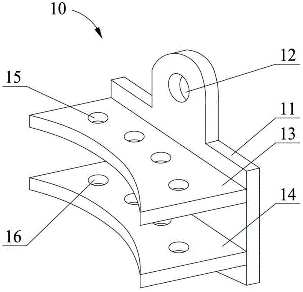
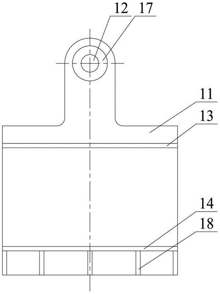
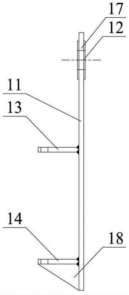
[0025] Embodiment one: this embodiment is based on Figure 4 The hoisting of the chemical equipment 20 shown in the vertical setting and the upper part is provided with a head flange 21 is taken as an example, and the structure and composition of the lifting lug 10 of the present invention are specifically described, as Figure 1 to Figure 3 As shown, it includes a lifting lug plate 11 with a hoisting hole 12 at one end arranged vertically; two splints arranged side by side and vertically fixed to the lug plate 11 respectively are an upper splint 13 and a lower splint 14, and the chemical equipment The head flange 21 of 20 can be embedded between the upper splint 13 and the lower splint 14, and the two splints 13, 14 are provided with bolts corresponding to the bolt holes (not shown in the figure) of the head flange 21. holes 15, 16, and the bolt holes 15, 16 of the two splints 13, 14 coincide with the axes of the bolt holes of the head flange 21, that is to say, the bolt hole...

Embodiment 2

[0033] Embodiment 2: Combination Figure 1 to Figure 5To illustrate the method of using the lifting lugs of the present invention, firstly, according to the loading position of the chemical equipment 10, install a pair of lifting lugs 10 on the horizontally symmetrical position of the head flange 21 of the chemical equipment 20. Specifically, remove the original connecting bolts at the head flange 21 of the chemical equipment 20, buckle a pair of lifting lugs 10 on the head flange 21 respectively, adjust and align the splints 13, 14 with the head method. The positions of the bolt holes of the flange 21 are then penetrated into the longer lifting bolts 19 for fastening, so that a pair of lifting lugs 10 are stably installed at the flange 21 of the head of the chemical equipment 20 . Before hoisting the chemical equipment 20, install shackles, hoisting balance beams, sling jacks and other lifting tools according to the hoisting process and construction plan requirements, and car...


PUM


Abstract

The invention discloses a lifting lug and a using method thereof, relating to the technical field of lifting cranes, and aiming at solving the problems that an existing fixed type lifting lug is welded together with an equipment body fixedly, and cannot be detached, so that the equipment manufacturing cost is increased, and the technology is relatively complex. The lifting lug comprises a lifting lug plate, two clamping plates and at least one pair of bolt holes, wherein one end of the lifting lug plate is provided with a lifting hole; the two clamping plates are arranged in parallel and are respectively fixedly connected with the lifting lug plate; a cover flange of chemical engineering equipment can be embedded between the two clamping plates; the two clamping plates are provided with at least one pair of corresponding bolt holes, and axes of the bolt holes of the two clamping plates are coincided with a bolt hole in the cover flange, so that the lifting lug and the cover flange can be connected together in a bolt mode.

Description

technical field [0001] The invention relates to the technical field of lifting and hoisting, in particular to a detachable plate-type lifting lug and a using method thereof. Background technique [0002] At present, in the domestic large-scale equipment hoisting process, there are mainly two types of fixed lifting lugs used in equipment hoisting: tube shaft type lifting lugs and plate type lifting lugs. These two kinds of lifting lugs need to be welded and fixed with the large equipment body in the actual application process, that is, the lifting lugs have been made and welded in place when the equipment is manufactured, and the fixed lifting lugs are specially customized according to non-standard equipment and cannot be disassembled, thus increasing The manufacturing cost of a single device is reduced. Moreover, before the equipment is manufactured, it is necessary to carry out the selection, design and review of the lifting lugs according to the weight and material of the...

Claims


Application Information

Patent Timeline
Patent Type & Authority Applications(China)
IPC IPC(8): B66C1/10
CPCB66C1/10
Inventor 倪志海曹智云
Owner SHANGHAI INSTALLATION ENG GRP
Why Eureka
Try Eureka