A hydraulic self-controlled cable retaining dam

A technology of hydraulic self-control and cable blocking, applied in water conservancy projects, marine engineering, coastline protection, etc., can solve problems such as affecting the viewing of river landscapes, unfavorable people's hydrophilicity, and near-water activities, and achieves remarkable economic practicability, construction Simple, technically mature effects

Active Publication Date: 2016-07-06
THE FRONTIER TECH RES INST OF TIANJIN UNIV
View PDF8 Cites 0 Cited by
  • Summary
  • Abstract
  • Description
  • Claims
  • Application Information

AI Technical Summary

Problems solved by technology

In order to protect the safety of people's lives and property, most rivers in our country have large flow, deep water and wide water surface under design flood conditions, while in non-flood periods, the flow is small, shallow and narrow, so higher embankments and larger A height difference of several meters is formed between the low water surfaces, which seriously affects the viewing of the river landscape and is not conducive to the people's water-friendly and near-water activities.

Method used


Image

  • A hydraulic self-controlled cable retaining dam
  • A hydraulic self-controlled cable retaining dam
  • A hydraulic self-controlled cable retaining dam

Examples


Embodiment

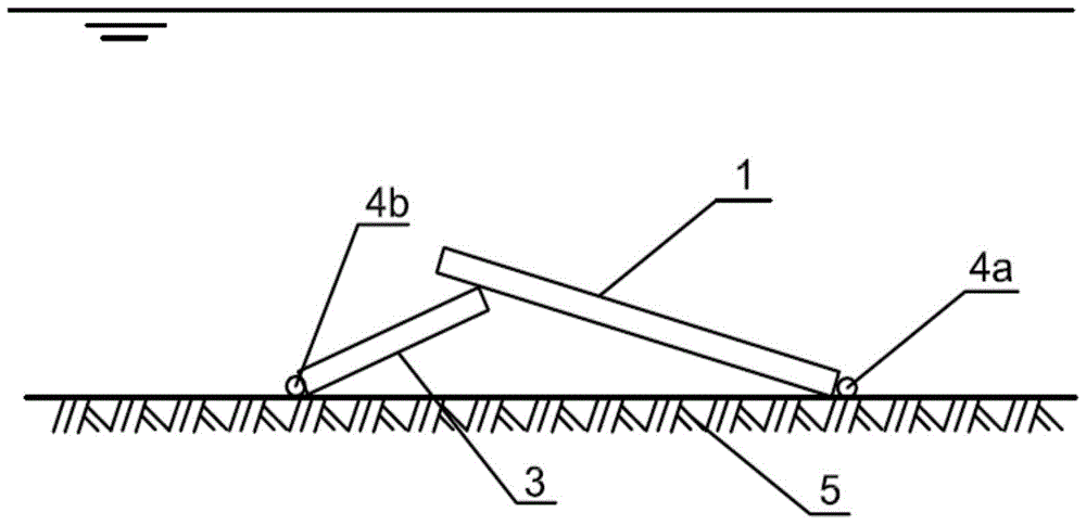
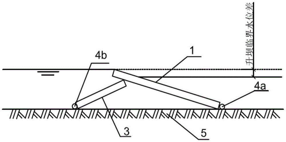
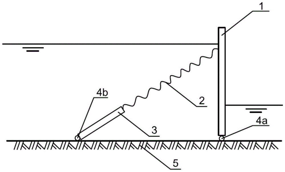
[0017] A hydraulic self-controlled cable retaining dam, such as Figure 1-5 As shown, it is arranged horizontally on the river bed 5 and adopts eight sections. The single-section retaining dam is composed of a water retaining steel plate 1, an elastic steel cable 2, a tie rod tube 3 and hinge supports 4a, 4b. The water retaining steel plate 1 is composed of two A sandwich structure composed of a rectangular parallelepiped steel plate, with vertical reinforcing ribs between the two steel plates, the water-retaining steel plate 1 is transversely hinged on the river bed 5 through the hinge support 4a, and one end of the elastic steel cable 2 is hinged on the river bed through the hinge support 4b. On the riverbed 5 on the upstream side of the water-retaining steel plate, the other end of the elastic steel cable 2 is fixed to the top of the water-retaining steel plate 1;

[0018] In this embodiment, the water-retaining steel plate is 5.0m wide, 2.5m high, and 0.3m thick, and the i...


PUM


Abstract

The invention discloses a hydraulic automatic-control water retaining dam with stay ropes. The hydraulic automatic-control water retaining dam is characterized in that the hydraulic automatic-control water retaining dam is transversely arranged on a riverbed and comprises a single section or a plurality of sections, each single section of the water retaining dam comprises a water retaining steel plate, the corresponding elastic steel stay rope, a draw bar barrel and hinge supports, each water retaining steel plate is of a sandwich structure which comprises two cuboid steel plates, perpendicular reinforcing ribs are arranged between each two layers of corresponding steel plates, the water retaining steel plates are transversely hinged onto the riverbed by the hinge supports, one end of each elastic steel stay rope is hinged onto the riverbed by the corresponding hinge support and is positioned on an upstream side of the corresponding water retaining steel plate, and the other end of each elastic steel stay rope is fixed to the upper portion of the corresponding water retaining steel plate; the draw bar barrels sleeve the elastic steel stay ropes, and the lower ends of the draw bar barrels are connected with the riverbed hinge supports of the steel stay ropes. The hydraulic automatic-control water retaining dam has the advantages that the hydraulic automatic-control water retaining dam can be manufactured in a standardized manner, and is reliable in quality, mature in technology, simple in construction and high in bearing capacity; the water retaining steel dam can be automatically lifted according to designed water level in water retaining periods, so that water can be retained; the water retaining steel dam can be automatically lowered down to be in an initial state in flood periods and accordingly is low in influence on flood draining in rivers and obvious in economic practicality.

Description

technical field [0001] The invention relates to a retaining dam in a water conservancy project, in particular to a retaining dam with a hydraulic self-control cable. Background technique [0002] In recent years, the demand for comprehensive improvement of rivers for the purpose of water environment and water ecological protection, as well as landscape and recreational environment creation has been increasing. In order to protect the safety of people's lives and property, most rivers in our country have large flow, deep water and wide water surface under design flood conditions, while in non-flood periods, the flow is small, shallow and narrow, so higher embankments and larger A height difference of several meters is formed between the low water surfaces, which seriously affects the viewing of the river landscape and is not conducive to the people's water-friendly and near-water activities. In order to improve the ecological beautification effect on both sides of the river ...

Claims


Application Information

Patent Timeline
Patent Type & Authority Patents(China)
IPC IPC(8): E02B7/40
CPCE02B7/40
Inventor 练继建张雅卓赵新张浦阳
Owner THE FRONTIER TECH RES INST OF TIANJIN UNIV
Why Eureka
Try Eureka