Cutting mechanism and heading machine

A cutting head and oil-feeding technology, which is applied in cutting machinery, mining equipment, earthwork drilling, etc., can solve problems such as difficult dust cleaning, affecting work efficiency, and bearing failure, so as to reduce the probability of entering the bearing cavity and improve The effect of working efficiency and prolonging the service life

Active Publication Date: 2015-03-25
SANY HEAVY EQUIP
View PDF4 Cites 4 Cited by
  • Summary
  • Abstract
  • Description
  • Claims
  • Application Information

AI Technical Summary

Problems solved by technology

[0004] On the one hand, during the oil injection process, it is necessary to manually rotate the cutting head multiple times to align the oil passage port, which is cumbersome, time-consuming and labor-intensive, and affects work efficiency
On the other hand, external dust will inevitably enter the floating seal frame through the gap between the tail of the cutting head and the telescopic part, causing some dust to accumulate at the oil inlet and overflow port of the floating seal frame. The dust is not easy to clean, so the dust easily enters the bearing chamber through the oil inlet and oil overflow port during the process of unscrewing the screw plug and filling oil, causing the bearing to fail prematurely

Method used


Image

  • Cutting mechanism and heading machine
  • Cutting mechanism and heading machine
  • Cutting mechanism and heading machine

Examples


Embodiment Construction

[0034] It should be noted that, in the case of no conflict, the embodiments of the present invention and the features in the embodiments can be combined with each other. Various preferred embodiments of the present invention will be further described below in conjunction with the accompanying drawings.

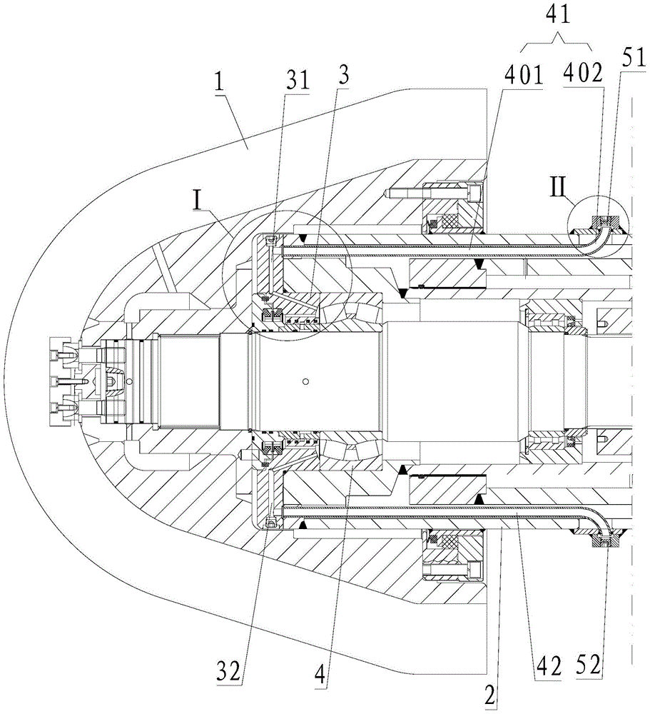
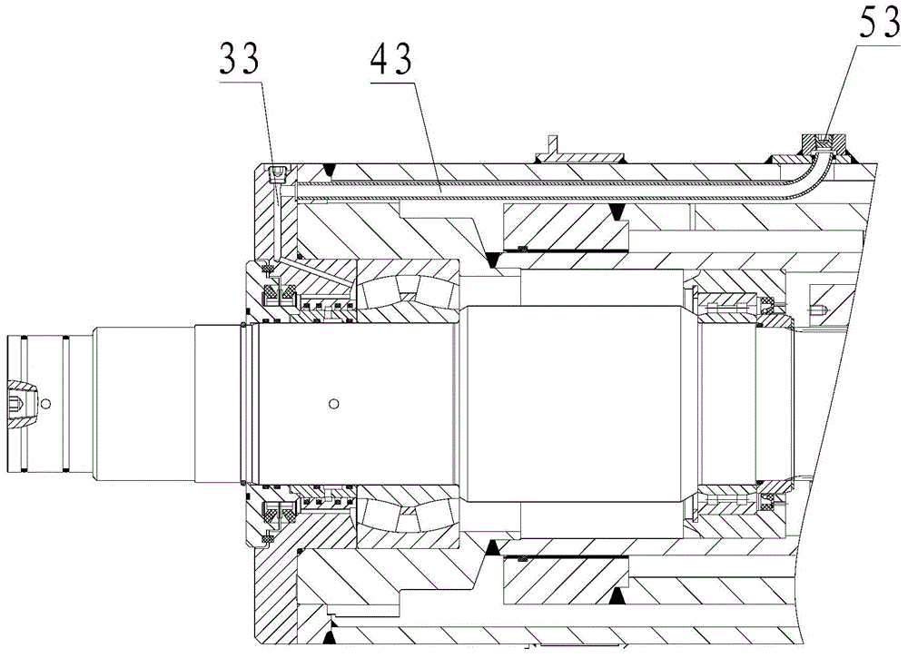
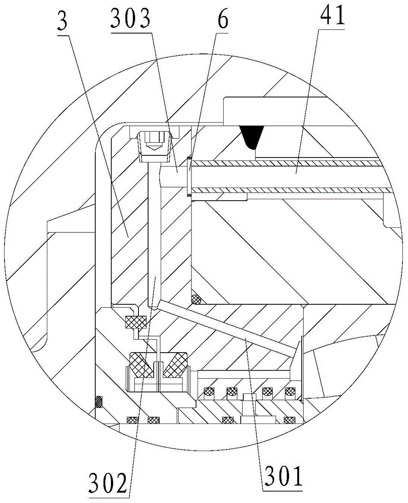
[0035] See figure 1 and figure 2 , which shows the structure of the cutting mechanism provided by the embodiment of the present invention. This cutting mechanism comprises cutting head 1, telescopic part, bearing 4 and floating seal frame 3; Floating seal frame 3 is provided with: oil inlet passage 31, oil discharge passage 32 and oil overflow passage 33; Oil inlet passage 31, The oil discharge passage 32 and the oil overflow passage 33 communicate with the bearing cavity of the bearing 4;

[0036] The cutting mechanism also includes:

[0037] Oil inlet pipeline 41, oil discharge pipeline 42 and oil overflow pipeline 43; communicated, and the other end communicates with ...


PUM


Abstract

The invention discloses a cutting mechanism and a heading machine. The cutting mechanism comprises a cutting head, a telescopic part, a bearing and a floating sealing frame, wherein an oil inlet path, an oil outlet path and an oil overflow path are formed in the floating sealing frame; the oil inlet path, the oil outlet path and the oil overflow path are communicated with a bearing cavity of the bearing; the cutting mechanism further comprises an oil inlet pipeline, an oil outlet pipeline and an oil overflow pipeline which are positioned between a telescopic protective barrel and a telescopic outer barrel of the telescopic part, or formed in the barrel wall of the telescopic protective barrel; one ends of the oil inlet pipeline, the oil outlet pipeline and the oil overflow pipeline respectively correspondingly communicated with the oil inlet path, the oil outlet path and the oil overflow path, and the other ends of the oil inlet pipeline, the oil outlet pipeline and the oil overflow pipeline are communicated with the outer part of the telescopic protective barrel; an oil inlet sealing part, an oil outlet sealing part and an oil overflow sealing part which are respectively arranged on end openings of the other ends of the oil inlet pipeline, the oil outlet pipeline and the oil overflow pipeline are used for selectively communicating or sealing the corresponding pipelines with the outside. The cutting mechanism has the advantages of convenience in oil injecting operation and oil exhausting operation, and the service life of the bearing is prolonged.

Description

technical field [0001] The invention relates to the field of engineering machinery, in particular to a cutting mechanism and a boring machine. Background technique [0002] The roadheader is a machine used to excavate straight underground roadways, and is mainly composed of a cutting mechanism, a loading and transferring mechanism, and a walking mechanism. During the working process, as the traveling mechanism advances, the cutting head in the cutting mechanism continuously breaks rocks and transports the broken rocks away. The roadheader has the advantages of safety, high efficiency and good roadway quality. Excavation and mining are important production links in coal mine production, and rapid excavation of coal mine roadways is a key technical measure for coal mines to ensure high and stable mine production. The mining technology and its equipment level directly affect the production capacity and safety of coal mines. In recent years, with the rapid development of my c...

Claims


Application Information

Patent Timeline
Patent Type & Authority Applications(China)
IPC IPC(8): E21C25/10E21D9/10
CPCE21C25/10E21D9/1006
Inventor 朱朋飞牛建强韩宇飞
Owner SANY HEAVY EQUIP
Why Eureka
Try Eureka