
Self-induction magnetic bearing

A magnetic bearing and self-induction technology, applied in bearings, shafts and bearings, mechanical equipment, etc., can solve the problems of increasing system cost and volume, high manufacturing cost, and high friction power consumption of mechanical bearings

Active Publication Date: 2015-03-25
JIANGSU UNIV OF TECH
View PDF8 Cites 3 Cited by
  • Summary
  • Abstract
  • Description
  • Claims
  • Application Information

AI Technical Summary

Problems solved by technology

Although the electromagnetic levitation bearing can realize active control, the production cost is high, the control system is complicated, and it also needs power supply; the superconducting magnetic levitation bearing does not need active control, but needs a low-temperature liquid nitrogen cooling system, which increases the system Cost and volume; frictional power consumption of mechanical bearings is large; permanent magnetic bearings do not require active control and are cheap, but permanent magnetic bearings cannot obtain stable suspension in all 6 degrees of freedom

Method used


Image

  • Self-induction magnetic bearing

Examples


Embodiment Construction

[0015] In order to make the content of the present invention easier to be understood clearly, the following further describes the present invention in detail based on specific embodiments in conjunction with the accompanying drawings.

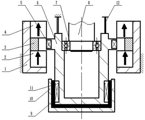
[0016] Such as figure 1 As shown, a self-induction magnetic bearing includes:

[0017] At least one magnetic pair assembly, which includes an upper permanent magnet ring 4, a magnetic isolation washer 3, and a lower permanent magnet ring 2. The magnetic isolation washer 3 is arranged between the upper permanent magnet ring 4 and the lower permanent magnet ring 2 for its Used to separate the upper permanent magnet ring 4 and the lower permanent magnet ring 2, the upper permanent magnet ring 4 and the lower permanent magnet ring 2 are both axially magnetized, and the upper permanent magnet ring 4 and the lower permanent magnet ring 2 are respectively connected with the magnetic isolation washer 3 The contacting side is the opposite magnetic pole; ...


PUM


Abstract

The invention discloses a self-induction magnetic bearing which comprises at least one magnetic pair assembly and a shaft neck, wherein each magnetic pair assembly comprises an upper permanent magnetic ring, a magnetic insulating gasket and a lower permanent magnetic ring, the magnetic insulating gasket is arranged between the upper permanent magnetic ring and the lower permanent magnetic ring and is used for separating the upper permanent magnetic ring from the lower permanent magnetic ring, the upper permanent magnetic ring and the lower permanent magnetic ring are both axially magnetized, and one surfaces, respectively in contact with the magnetic insulating gasket, of the upper permanent magnetic ring and the lower permanent magnetic ring are opposite magnetic poles; and the shaft neck can oscillate in the radial direction, the inside of the shaft neck is used for rotationally supporting a rotating shaft, the outer wall of the shaft neck is provided with at least one induction coil, the induction coils correspond to the magnetic pair assemblies one by one, the induction coils are arranged between the corresponding upper permanent magnetic ring and lower permanent magnetic ring, an annular gap between the lower end of the shaft neck and a magnetic insulating shell is filled with magnetorheological fluid, an electromagnetic coil and the induction coils are communicated, and the electromagnetic coil is arranged in the magnetorheological fluid. The bearing disclosed by the invention can run without active control, does not have friction loss, and has a self-induction function, thereby ensuring the efficient and stable running of rotors under high-speed working condition.

Description

Technical field [0001] The invention relates to a self-induction magnetic bearing, a bearing device that radially supports and provides damping for the key component rotor of high-speed rotating machinery (such as centrifuges, turbines, energy storage flywheels, etc.), and belongs to the technology of equipment manufacturing field. Background technique [0002] At present, in order to ensure that the shaft system can operate stably and efficiently, in various high-speed rotating machinery such as centrifuges, turbines, and energy storage flywheels, various low-power bearings are often used to support the rotor. On the other hand, in order to ensure the rotor -The stable operation of the bearing system also requires the introduction of a damping device in the shaft system. [0003] Commonly used bearings are-superconducting magnetic levitation, electromagnetic levitation, permanent magnetic levitation and mechanical bearings. Although the electromagnetic suspension bearing can...

Claims


Application Information

Patent Timeline
Patent Type & Authority Applications(China)
IPC IPC(8): F16C32/04
Inventor 王洪昌
Owner JIANGSU UNIV OF TECH
Learn More