
Magneto-rheological damper with effective full-damping channel

A magnetorheological damper and damper technology, applied in the field of damping and vibration reduction, can solve the problems of increasing the volume and weight of the damper, reducing the maximum output of the magnetorheological damper, etc.

Active Publication Date: 2016-07-20
河南省建设工程施工图审查中心有限公司
View PDF5 Cites 2 Cited by
  • Summary
  • Abstract
  • Description
  • Claims
  • Application Information

AI Technical Summary

Problems solved by technology

However, the traditional shear valve magnetorheological damper has a groove on the piston, and the excitation coil is wound in the groove. Due to the limitation of the wire diameter and the number of turns in the excitation coil, the groove usually accounts for more than 1 / 2 of the total length of the piston. , since the damping channel in the groove part of the winding excitation coil has no magnetic field, it is an ineffective length, which not only increases the volume and weight of the damper, but also reduces the maximum output of the magnetorheological damper, and the maximum output loss is about 50%.

Method used


Image

  • Magneto-rheological damper with effective full-damping channel
  • Magneto-rheological damper with effective full-damping channel
  • Magneto-rheological damper with effective full-damping channel

Examples


Embodiment Construction

[0017] The technical solution of the present invention will be described in further detail below with reference to the accompanying drawings and embodiments.

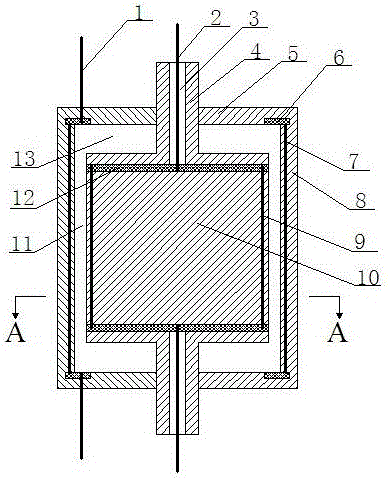
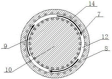
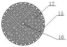
[0018] Such as figure 1 , 2 , 3, and 4, the effective magneto-rheological damper of the full damping channel includes a damper cylinder 8 and a piston body 10, the upper and lower ends of the damper cylinder are fixedly connected with end caps 5 by bolts, and the piston body is set Inside the damper cylinder and symmetrically installed at both ends are piston rods 4 protruding from both ends of the damper cylinder. The piston rod and the piston body are fixedly connected by bolts. The central axis of the piston rod, the piston body and the damper cylinder Coincident; the upper and lower parts of the piston body are symmetrically arranged with a disc-shaped hub A12 along the axis of the piston body, the diameter of the hub A is slightly smaller than the diameter of the piston body, and the outer edges of the two hubs A ...


PUM


Abstract

The invention discloses a magneto-rheological damper with an effective full-damping channel. The magneto-rheological damper comprises a damper cylinder barrel and a piston body; piston rods extending out of end covers of the damper cylinder barrel are installed at the two ends of the piston body; wire concentration plates A are symmetrically arranged at the upper portion and the lower portion of the piston body, straight wires A which are evenly distributed in the peripheral direction of the piston body are connected between the outer edges of the two wire concentration plates A, and two total inner wires connected with the two wire concentration plates A are led out from wire leading-out holes in the piston rods; wire concentration plates B are symmetrically arranged in end covers of the two ends of the damper cylinder barrel, straight wires B which are evenly distributed in the peripheral direction of the damper cylinder barrel are connected between the outer edges of the two wire concentration plates B, and two total outer wires connected with the two wire concentration plates B extend out from the end covers; and space among the damper cylinder barrel, the piston rods and the piston body is filled with magneto-rheological fluid, and an annular gap between the damper cylinder barrel and the piston body is the damping channel. By means of the magneto-rheological damper, the overall-length effective damping channel is achieved, and the maximum output of the magneto-rheological damper is improved to the greatest degree.

Description

technical field [0001] The invention belongs to the technical field of damping and vibration reduction, and relates to a magnetorheological damper, in particular to a magnetorheological damper with effective full damping channels. Background technique [0002] Magneto-rheological dampers have the characteristics of millisecond-level response speed, large control range and large damping force output, and have become excellent semi-active actuators in industrial applications. At present, magnetorheological dampers have been widely used in vibration reduction and anti-seismic systems of buildings and bridges, and vibration reduction of railway rolling stock and automobile suspension systems. [0003] The magnetorheological damper is a semi-active control device manufactured by using the magnetorheological fluid to realize the liquid-solid two-phase inversion characteristics in a short time (milliseconds) under the action of a magnetic field. According to the stress state and f...

Claims


Application Information

Patent Timeline
IPC IPC(8): F16F9/53F16F9/32
CPCF16F9/3207F16F9/535
Inventor 张香成周甲佳赵军李倩
Owner 河南省建设工程施工图审查中心有限公司
Learn More