Floating type brake pad

A brake pad, floating technology, applied in the direction of brake parts, friction linings, mechanical equipment, etc., can solve the problems of poor braking performance, unstable thermoelasticity, short life of the brake disc, etc. Improved performance, improved braking stability, and prevention of fatigue fractures

Inactive Publication Date: 2015-03-25
BEIJING TIANYISHANGJIA NEW MATERIAL
View PDF7 Cites 20 Cited by
  • Summary
  • Abstract
  • Description
  • Claims
  • Application Information

AI Technical Summary

Problems solved by technology

[0005] For this reason, the technical problem to be solved by the present invention is that the thermoelastic instability of the existing train brake pads leads to poor braking performance and short service life of the brake disc, and then provides a method that can stably and reliably make the friction block and Brake pads with good fit of the brake disc and maximum avoidance of eccentric wear of the friction block and less thermal deformation of the brake disc

Method used


Image

  • Floating type brake pad
  • Floating type brake pad
  • Floating type brake pad

Examples


Embodiment Construction

[0026] In the following, the present invention will be further described by using the following embodiments in conjunction with the accompanying drawings.

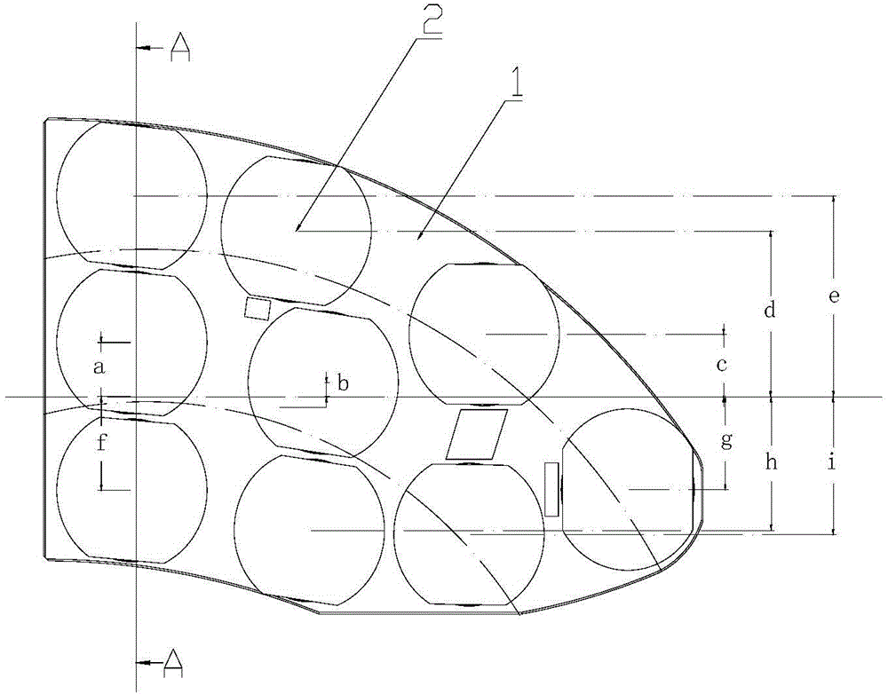
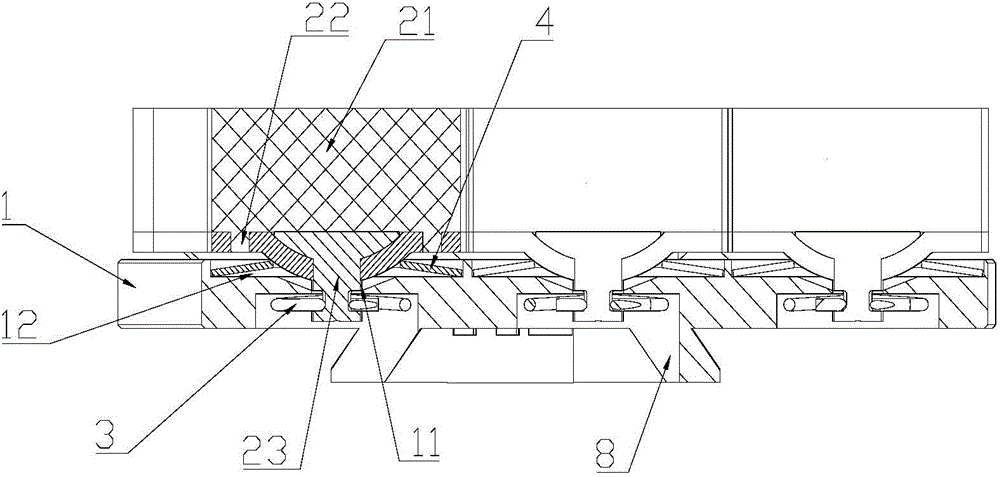
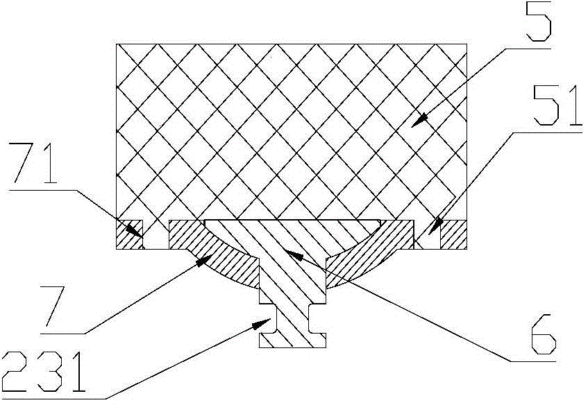
[0027] figure 1 , figure 2 It is a floating brake pad of the present invention, which includes a back plate formed by splicing and connecting two back plates 1; several friction blocks 2 arranged on the back plate 1; 2 and the disc spring 4 between the back plate 1, and the clip spring 3 that connects the friction block 2 to the back plate 1 in a floating manner. Such as figure 1 As shown, with the virtual center of the backplane 1 as the center, the backplane 1 is divided into three rings (rings separated by arc-shaped dotted lines in the figure), and the three rings The lengths along the radial direction are equal, and the friction area of ​​the friction block 2 in each said ring is no more than 12% of the reference average friction area compared with the reference average friction area, that is, the friction area of...


PUM


Abstract

The invention discloses a floating type brake pad. The floating type brake pad comprises a back plate, a plurality of friction blocks, disc springs and clamping springs, wherein the friction blocks are arranged on the back plate, the disc springs are arranged between the friction blocks and the back plate, and the friction blocks are connected to the first back plate in a floating mode through the clamping springs. Positioning grooves are formed in the back plate, and the disc springs are arranged inside the positioning grooves. The back plate is divided into a plurality of concentric circular rings by using the circle center of a brake disc matched with the brake pad as the circle center. The circular rings are equal in radial length. The friction area of the friction block inside each circular ring is not larger than 15% of the standard average friction area compared with the standard average friction area. According to the floating type brake pad, the problem of fatigue cracks caused by instantaneous stress concentration during braking of existing disc springs is solved, meanwhile, gaps between the back plate and the friction blocks are reduced, oscillation of the friction blocks is small, meanwhile, the problem of eccentric abrasion of the friction blocks is avoided, and the brake stability is greatly improved.

Description

technical field [0001] The invention relates to a disc brake device applied to high-speed trains, in particular to a floating brake pad. Background technique [0002] In the train disc brake system, the brake pad is one of the key components. The braking force is applied to the brake pad through the brake caliper, so that the friction block of the brake pad contacts the brake disc to absorb kinetic energy. Make the train brake to stop. When the friction block is in contact with the brake disc and slides relative to each other, frictional heat will be generated on the sliding surface. Frictional heat causes thermal deformation of the two at the contact surfaces. Thermal deformation in turn affects the contact pressure distribution between the friction surfaces. For a given coefficient of friction, there is a certain critical sliding velocity of the brake disc, above which the nominally evenly distributed contact pressure becomes unstable, creating pressure and friction in ...

Claims


Application Information

Patent Timeline
Patent Type & Authority Applications(China)
IPC IPC(8): F16D65/04F16D69/04
Inventor 吴佩芳
Owner BEIJING TIANYISHANGJIA NEW MATERIAL
Why Eureka
Try Eureka