Brake pad

A technology of brake pads and brake pads, which is applied in the direction of friction linings, mechanical equipment, etc., can solve problems such as thermoelastic instability, short life of brake discs, and poor braking performance, and achieve improved braking performance and improved heat flow. Consistent density and improved service life

Active Publication Date: 2015-04-08
BEIJING TIANYISHANGJIA NEW MATERIAL
View PDF10 Cites 3 Cited by
  • Summary
  • Abstract
  • Description
  • Claims
  • Application Information

AI Technical Summary

Problems solved by technology

[0005] For this reason, the technical problem to be solved by the present invention is that the thermoelastic instability of the existing train brake discs leads to poor braking performance and short service life of the brake discs, and then provides a brake disc with less thermal deformation. brake pads

Method used


Image

  • Brake pad
  • Brake pad
  • Brake pad

Examples


Embodiment 1

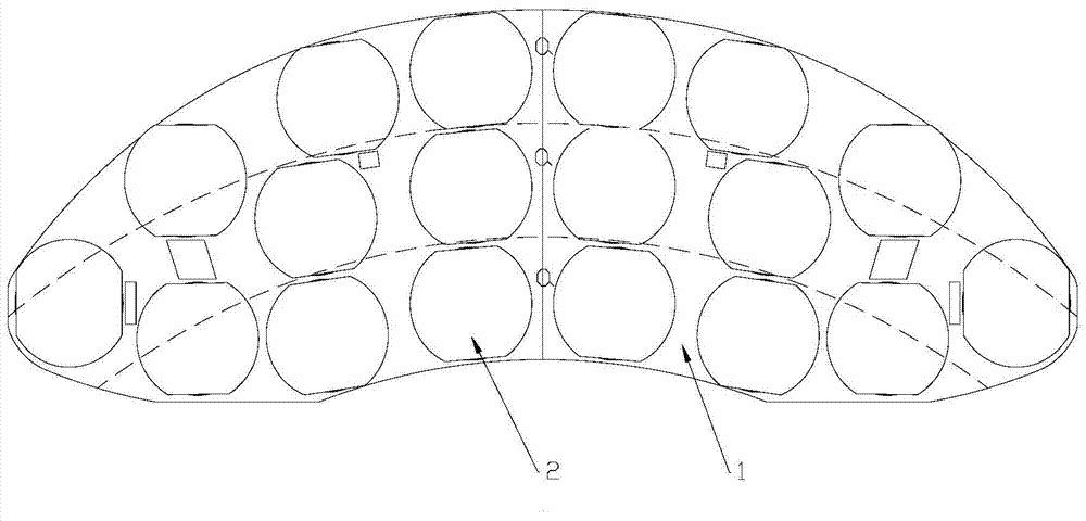
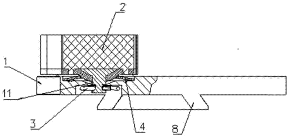
[0031] Figure 1-4 It is the brake pad of the present invention, which includes a back plate 1, two of which are spliced ​​into a brake pad back plate; several friction blocks 2 arranged on the back plate 1; and the friction blocks 2 connected to the snap spring 3 on the backboard 1; as figure 1 As shown, taking the virtual center of the backplane 1 as the center, the backplane 1 is divided into three rings a, the lengths of the three rings a in the radial direction are equal, and each of the rings a The friction area of ​​the friction block 2 inside is no more than 12% of the reference average friction area compared with the reference average friction area, that is, the friction areas of equidistant rings are approximately equal. The arrangement structure of the friction blocks can make the heat flux density of the back plate consistent, and the friction heat generated by the friction blocks during braking can be evenly distributed on the back plate, which avoids the back pl...

Embodiment 2

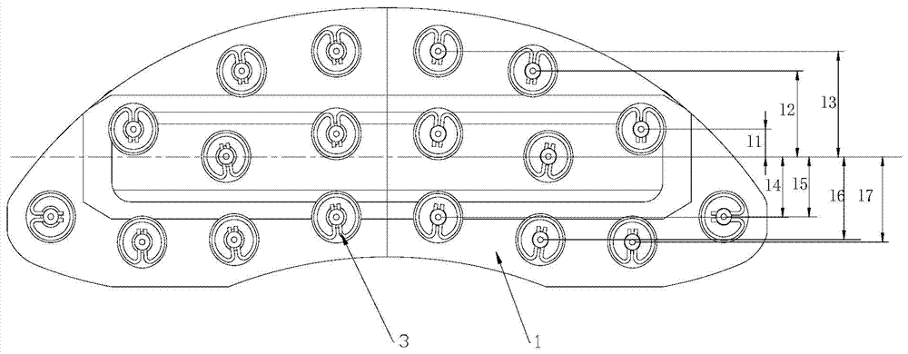
[0039] On the basis of Embodiment 1, in this embodiment, the distance between the friction blocks 2 on both sides of the brake pads and the stressed centerline of the brake pads is centered on the stressed centerline of the brake pads Compared with the reference distance, the sum does not exceed 10% of the reference distance. Such as Figure 5 As mentioned above, since the brake pad A is installed on the brake pad support D, and the brake caliper B and the brake pad support D are connected through the joint C, the axis of the joint C constitutes the joint of the present invention. Brake force center line.

[0040] For the brake pads in this embodiment, since the friction block is arranged symmetrically on the back plate 1, the sum of the distances from the friction block 2 to the force center line of the brake pad can be passed through the left side or The friction block on the right is calculated as figure 2 As shown, among the five friction blocks on the right side, the ...

Embodiment 3

[0043] The structure of this embodiment is basically the same as that of Embodiment 2, the difference is that in this embodiment, the outer contour of the friction block 2 is located inside the outer contour of the back plate 1 or is in line with the outer contour of the back plate 1 cut.

[0044] In other embodiments, the brake pads take the center of the brake disc as the center to divide the back plate 1 into several equidistant rings a, and the friction blocks in each ring a The friction areas of 2 are equal; with the center line of the brake pad as the center, the sum of the distances between the friction blocks 2 on both sides and the center line of the brake pad is equal; the above scheme is the ideal state of the present invention. Considering the processing cost of the brake pad comprehensively, the brake pad takes the center of the brake disc as the center, divides the back plate 1 into a plurality of equidistant rings a, each of the rings a The friction area of ​​t...


PUM


Abstract

The invention discloses a brake pad. The brake pad comprises a back plate (1) and a plurality of friction blocks (2). A plurality of positioning holes (11) are formed in the back plate (1), and the friction blocks which are mounted on the back plate (1) are inserted into the positioning holes (11) and connected onto the back plate (1) through a plurality of snap springs (3) arranged on the other side of the back plate (1). The back plate (1) is partitioned into a plurality of circular rings (a) by centering on the center of a circle of a brake disc matched with the brake pad, the circular rings (a) are radially equal in length, and the friction area of the friction blocks (2) in each circular ring (a) is not more than and not less than 15% of a standard average friction area. The brake pad has the advantage that the problems of short service life and poor brake stability of an existing brake pad due to instable thermoelasticity are solved.

Description

technical field [0001] The invention relates to a disc brake device applied to high-speed trains, in particular to a brake pad. Background technique [0002] In the train disc brake system, the brake pad is one of the key components. The braking force is applied to the brake pad through the brake caliper, so that the friction block of the brake pad contacts the brake disc to absorb kinetic energy. Make the train brake to stop. When the friction block is in contact with the brake disc and slides relative to each other, frictional heat will be generated on the sliding surface. Frictional heat causes thermal deformation of the two at the contact surfaces. Thermal deformation in turn affects the contact pressure distribution between the friction surfaces. For a given coefficient of friction, there is a certain critical sliding velocity of the brake disc, above which the nominally evenly distributed contact pressure becomes unstable, creating pressure and friction in localized...

Claims


Application Information

Patent Timeline
Patent Type & Authority Applications(China)
IPC IPC(8): F16D69/04
Inventor 吴佩芳
Owner BEIJING TIANYISHANGJIA NEW MATERIAL
Why Eureka
Try Eureka