Floating type brake pad
A brake pad, floating technology, applied in the direction of brake parts, friction linings, mechanical equipment, etc., can solve the problems of unstable thermoelasticity, poor braking performance, short life of brake discs, etc. Improved performance, increased service life, consistent heat flux
- Summary
- Abstract
- Description
- Claims
- Application Information
AI Technical Summary
Problems solved by technology
Method used
Image
Examples
Embodiment 1
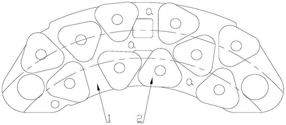
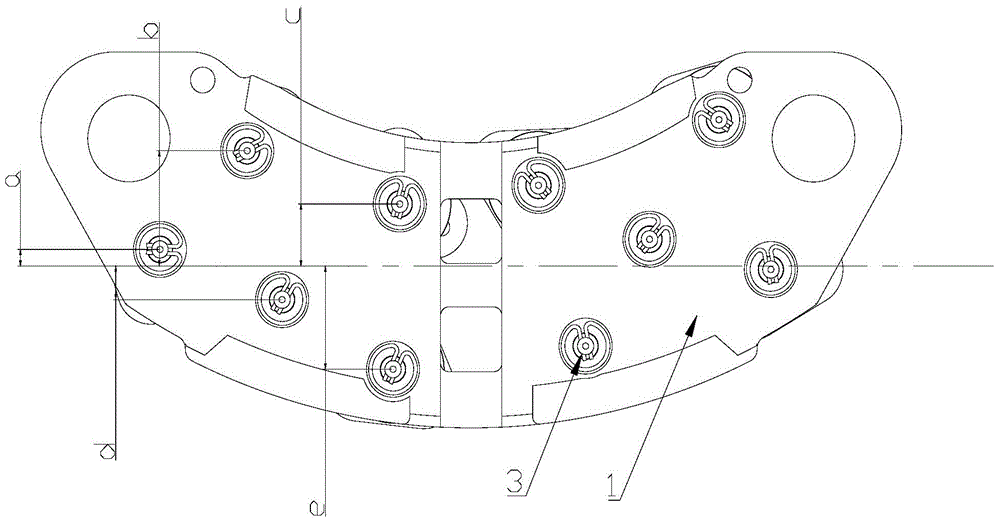
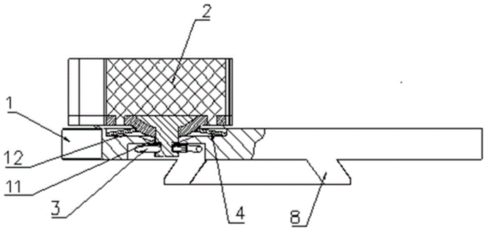
[0028] Figure 1-4 It is a floating brake pad of the present invention, which includes a back plate 1; several friction blocks 2 arranged on the back plate 1; and a retaining spring connecting the friction blocks 2 to the back plate 1 3; if figure 1 As shown, taking the virtual center of the backplane 1 as the center, the backplane 1 is divided into three rings a, the lengths of the three rings a in the radial direction are equal, and each of the rings a The friction area of the friction block 2 inside is no more than 12% of the reference average friction area compared with the reference average friction area, that is, the friction areas of equidistant rings are approximately equal. The arrangement structure of the friction blocks can make the heat flux density of the back plate consistent, and the friction heat generated by the friction blocks during braking can be evenly distributed on the back plate, which avoids the excessive temperature gradient of the existing floatin...
Embodiment 2
[0036] On the basis of Embodiment 1, in this embodiment, in the floating brake pad, the center line of the brake pad is centered, and the distance between the friction blocks 2 on both sides of the brake pad is the center line of the brake pad. Compared with the reference distance, the sum of the distances does not exceed 10% of the reference distance. Such as Figure 5 As mentioned above, since the brake pad A is installed on the brake pad support D, and the brake caliper B and the brake pad support D are connected through the joint C, the axis of the joint C constitutes the joint of the present invention. Brake force center line.
[0037] In this embodiment, for the floating brake pad, since the friction block is arranged symmetrically on the back plate 1, the sum of the distances from the friction block 2 to the force center line of the brake pad can be obtained by left side or right friction block calculation, such as figure 2 As shown, among the five friction blocks o...
Embodiment 3
[0040] The structure of this embodiment is basically the same as that of Embodiment 2, the difference is that in this embodiment, the outer contour of the friction block 2 is located inside the outer contour of the back plate 1 or is in line with the outer contour of the back plate 1 cut.
[0041] In other embodiments, the floating brake pad takes the center of the brake disc as the center, and divides the back plate 1 into several equidistant rings a, and each of the rings a in the ring a The friction areas of the friction blocks 2 are equal; with the center line of the brake pads as the center, the sum of the distances between the friction blocks 2 on both sides and the center line of the brake pads is equal; the above scheme is the ideal state of the present invention. Considering the processing cost of the floating brake pad comprehensively, the floating brake pad takes the center of the brake disc as the center and divides the back plate 1 into several equidistant rings a...
PUM
 Abstract
Description
Claims
Application Information
 - R&D
- Intellectual Property
- Life Sciences
- Materials
- Tech Scout
- Unparalleled Data Quality
- Higher Quality Content
- 60% Fewer Hallucinations
Browse by: Latest US Patents, China's latest patents, Technical Efficacy Thesaurus, Application Domain, Technology Topic, Popular Technical Reports.
© 2025 PatSnap. All rights reserved.Legal|Privacy policy|Modern Slavery Act Transparency Statement|Sitemap|About US| Contact US: help@patsnap.com


