The design structure of inlet side to side of 1500℃ ultra-high temperature angle globe valve

An angle-type globe valve and a technology of designing a structure, which is applied in the field of valve manufacturing, can solve the problems of large heat loss of the medium, no retrieval, and the medium at the outlet of the valve cannot meet the requirements of the test, etc., and achieves the effect of reducing potential safety hazards.

Active Publication Date: 2017-01-11
LANZHOU HIGH PRESSURE VALVE
View PDF5 Cites 0 Cited by
  • Summary
  • Abstract
  • Description
  • Claims
  • Application Information

AI Technical Summary

Problems solved by technology

[0002] For high-temperature valves with lower temperature levels around 800 °C, there are valves made of non-metals at home and abroad, but due to the properties of non-metallic materials, they cannot meet the requirements of rapid cooling, rapid heating and high pressure conditions.
At home and abroad, water cooling measures are used to make the valve work normally, but this will cause too much heat loss of the medium, and the medium at the outlet of the valve will not meet the test requirements, so it cannot be used.
According to the current domestic and foreign relevant data, in the field of high temperature resistance, there is no valve that can work safely under the high temperature, high pressure and high speed working condition of 1500 ℃, especially no valves with particulate matter and dust in the medium under the high temperature high pressure high speed working condition of 1500 ℃ have been retrieved. There is no valve that can work safely when there is slag, and the above-mentioned corresponding ultra-high temperature valve is designed with a slag collecting tank and an observation window.

Method used


Image

  • The design structure of inlet side to side of 1500℃ ultra-high temperature angle globe valve
  • The design structure of inlet side to side of 1500℃ ultra-high temperature angle globe valve
  • The design structure of inlet side to side of 1500℃ ultra-high temperature angle globe valve

Examples


Embodiment Construction

[0024] The present invention will be described in detail below in conjunction with the accompanying drawings and specific embodiments.

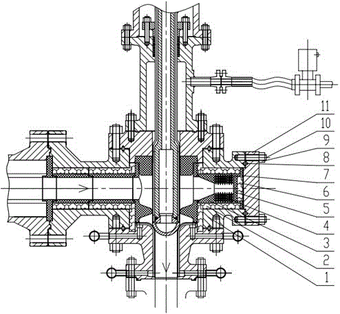
[0025] See figure 1 , a 1500°C ultra-high temperature angle stop valve inlet side-to-side design structure, characterized in that: the main valve body 1 on the side opposite to the inlet end of the angle stop valve is provided with a slag collection tank, the slag collection tank also has The role of the observation window.

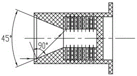
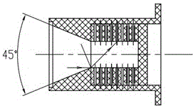
[0026] The slag collecting tank includes a collecting cone ring 3, which is installed at the main valve body 1 on the opposite side of the inlet end of the angle stop valve, and a heat insulating ring 2 is arranged between them; the collecting cone ring The front end of 3 is a cone structure, and the rear end is a column structure, in which the slag collection bucket 4, wear plate 5, heat insulation plate 6, buffer plate 7 are installed in sequence, and then the end cover 11 passes through the seal 8 and the nuts and bo...


PUM


Abstract

The invention discloses a designing structure of a 1500 DEG C ultrahigh-temperature angle stop valve inlet end opposite side. A slag collecting groove is formed in a main valve body of the angle stop valve inlet end opposite side, plays a role as an observation window and comprises a collecting conical ring which is mounted at the main valve body of the angle stop valve inlet end opposite side, a heat insulating ring is arranged between the collecting conical ring and the main valve body, the front end of the collecting conical ring is of a conical structure while the rear end of the same is of a cylindrical structure, a slag collecting barrel, a wear-resistant plate, a heat-insulating plate and a buffering plate are sequentially mounted on the collecting conical ring which is hermetically fixed on the main valve body by an end cap, and holes are uniformly distributed in the wall of the slag collecting barrel. Particles and ash in a high-temperature medium are fully collected, and an observation window structure is arranged, so that convenience is brought to demounting and mounting; under the circumstance that a valve rod and a valve cover are not demounted, convenience is brought to observing working conditions of a valve inner cavity, a valve rod head and a valve seat sealing face online so as to timely maintain and replace to lower potential safety hazards.

Description

technical field [0001] The invention belongs to the technical field of valve manufacturing, and relates to a design structure of the opposite side of the inlet end of an angle stop valve, which is satisfied with ultra-high-temperature, high-velocity high-temperature air with particles and ash. Background technique [0002] For high-temperature valves with a lower temperature level of around 800 °C, there are valves made entirely of non-metal at home and abroad, but due to the properties of non-metal materials, they cannot meet the requirements of rapid cooling, rapid heating and high-pressure working conditions. At home and abroad, water cooling measures are used to make the valve work normally, but this will cause too much heat loss of the medium, and the medium at the outlet of the valve will not meet the requirements of the test, so it cannot be used. According to the current domestic and foreign relevant data, in the field of high temperature resistance, there is no valv...

Claims


Application Information

Patent Timeline
Patent Type & Authority Patents(China)
IPC IPC(8): F16K1/32F16K27/02
CPCF16K1/32F16K27/02
Inventor 陈文鑫陈清流董霞张琳乐精华
Owner LANZHOU HIGH PRESSURE VALVE
Why Eureka
Try Eureka