Heavy duty adjustable swivel feet

A support foot and heavy-duty technology, which is applied in the field of support feet of heavy equipment, can solve the problems that the equipment cannot be guaranteed to move up and down, left and right, front and back accurately, and achieve the effect of precise adjustment and positioning and cost saving

Inactive Publication Date: 2016-03-23
GANZHOU NONFERROUS METALLURGICAL MACHINERY
View PDF6 Cites 0 Cited by
  • Summary
  • Abstract
  • Description
  • Claims
  • Application Information

AI Technical Summary

Problems solved by technology

[0003] The purpose of the present invention is to provide a heavy-duty adjustable universal support foot, which overcomes the shortcomings that the existing support cannot ensure that the equipment needs to move up and down, left and right, and front and back accurately.

Method used


Image

  • Heavy duty adjustable swivel feet
  • Heavy duty adjustable swivel feet
  • Heavy duty adjustable swivel feet

Examples


Embodiment Construction

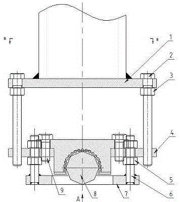
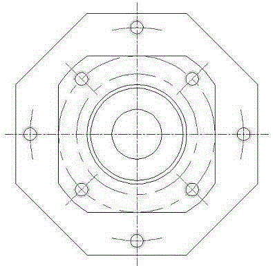
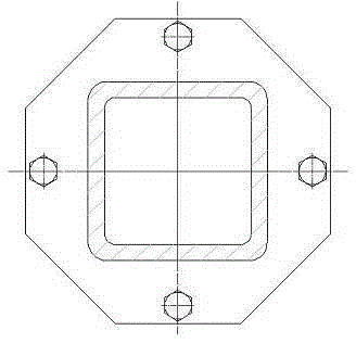
[0010] Now in conjunction with accompanying drawing and embodiment the present invention will be further described:

[0011] As shown in the figure: a heavy-duty adjustable universal foot, which is characterized in that it includes a lower mounting plate 7, a universal ball bearing 8, a lower adjusting screw 6, a middle plate 4, an upper adjusting screw 2 and an equipment foot plate 1, the lower The mounting plate 7 is connected and fixed together with the lower adjusting screw 6, the universal ball bearing 8 is installed on the middle plate 4 through the universal ball bearing mounting bolt 9, and the equipment foot plate 1 is connected with the middle plate 4 through the upper adjusting screw 2. Rotate the lower adjusting nut 5 to lift the lower mounting plate 7 off the ground, and then rotate the upper adjusting screw 2 and the upper adjusting nut 3 to adjust the equipment foot plate 1 and the equipment to a suitable installation height. At this time, the universal ball bear...


PUM


Abstract

An adjustable universal stand bar for heavy equipment is characterized by comprising a lower installation plate, a universal ball bearing, a lower adjusting screw, an intermediate plate, an upper adjusting screw and an equipment stand bar plate, the universal ball bearing is used for achieving supporting, the upper adjusting screw is used for adjusting height, the lower adjusting screw is used for adjusting the lower installation plate to serve as a final support, the universal ball bearing can move forwards, backwards, leftwards and rightwards, and due to the adoption of rolling friction, resistance is small, and micro-adjustment can be achieved; the upper adjusting screw enables rising and falling of the heavy equipment to be achieved directly, the lower adjusting screw can be adjusted to enable the lower installation plate to make contact with the ground, final positioning after adjustment is finished can be achieved, the universal ball bearing can be taken out after positioning, and cost is reduced. By the adoption of the adjustable universal stand bar for the heavy equipment, accurate adjustment and positioning of the heavy equipment during manufacturing and installation can be achieved.

Description

technical field [0001] The invention relates to a support foot for heavy equipment. Background technique [0002] The existing supporting feet of heavy equipment are generally installed with flat plates or casters for support, which cannot guarantee that the equipment needs to move up and down, left and right, and front and back accurately. The feet can only move in one direction, so it is not easy to change up and down, and the adjustment is also troublesome. Contents of the invention [0003] The purpose of the present invention is to provide a heavy-duty adjustable universal support foot, which overcomes the disadvantage that the existing support cannot ensure that the equipment needs to move up and down, left and right, and front and back accurately. [0004] A heavy-duty adjustable universal foot, characterized in that it includes a lower mounting plate, a universal ball bearing, a lower adjusting screw, a middle plate, an upper adjusting screw and an equipment foot ...

Claims


Application Information

Patent Timeline
Patent Type & Authority Patents(China)
IPC IPC(8): F16M7/00
Inventor 刘毅谢振兴
Owner GANZHOU NONFERROUS METALLURGICAL MACHINERY
Why Eureka
Try Eureka