Eureka AIR delivers breakthrough ideas for toughest innovation challenges, trusted by R&D personnel around the world.

Optical receiving and sending structure for short-distance laser distance measuring instrument

A laser range finder and short-range technology, which is used in line-of-sight measurement, distance measurement, instruments, etc., can solve problems such as the inability of laser range finder to work, and achieve the effects of miniaturization, reduction of occupied volume, and improvement of capabilities.

Active Publication Date: 2015-03-25
BEIJING AEROSPACE INST FOR METROLOGY & MEASUREMENT TECH +1
View PDF9 Cites 3 Cited by
  • Summary
  • Abstract
  • Description
  • Claims
  • Application Information

AI Technical Summary

Problems solved by technology

[0004] The object of the present invention is to provide an optical transmission structure for a short-distance laser rangefinder to solve the problem that the above-mentioned laser rangefinder cannot work when measuring a short-distance distance. Through this structure, it can be as close as possible to the coaxial situation, thereby improving the ability of short-distance detection, and at the same time, it can be cut to reduce the size of the lens, which is conducive to the miniaturization of the instrument

Method used


Image

  • Optical receiving and sending structure for short-distance laser distance measuring instrument
  • Optical receiving and sending structure for short-distance laser distance measuring instrument
  • Optical receiving and sending structure for short-distance laser distance measuring instrument

Examples


Embodiment Construction

[0017] The present invention will be described in detail below in conjunction with the accompanying drawings and specific embodiments.

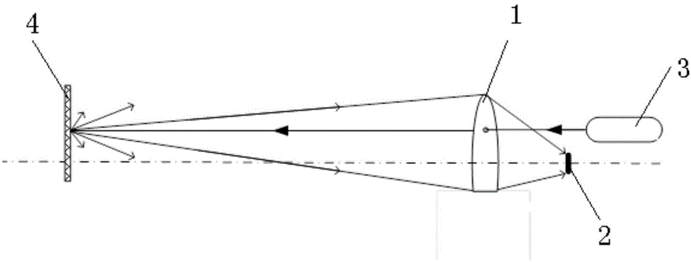
[0018] Such as figure 1 As shown, the optical transmitting and receiving structure for the short-distance laser rangefinder of the present invention is as follows: the light beam emitted by the laser 3 is emitted through the off-axis through hole on the receiving lens 1, and diffuse reflection occurs after encountering the target object 4, The reflected light is collected by the receiving lens 1 and converged onto the detector 2 located on the back focal plane.

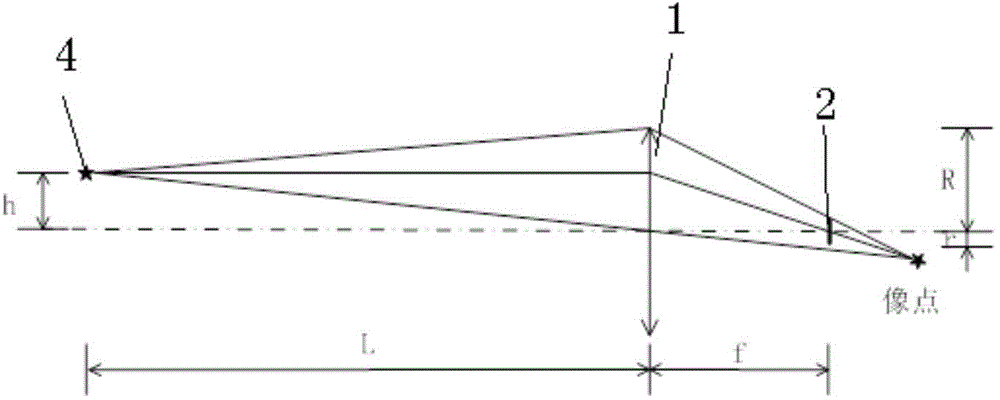
[0019] The implementation method of the above structure is as follows: figure 2 As shown, firstly, according to the focal length f of the selected receiving lens 1 and the size r of the sensitive surface of the detector 2, the off-axis distance h that the converging light can cover the entire detection surface when the shortest detection distance is L is calculated according to the...


PUM


Abstract

The invention belongs to the technical field of optical system design, and particularly relates to an optical receiving and sending structure for a short-distance laser distance measuring instrument. A light beam sent by a laser is sent out through an off-axis through hole formed in a receiving lens and subjected to diffuse reflection after encountering a target object, and reflected light collected through the receiving lens can be gathered to a detector positioned on a rear focal plane; the light beam sent by the laser is parallel to the axial line of the receiving lens; and the off-axis distance h of the off-axis through hole formed in the receiving lens is determined according to the following method: on the basis of the selected focal distance f of the receiving lens and the sensitive surface size r of the detector, the off-axis distance h is calculated when the gathered light can cover a whole detection surface with the shortest detection distance being L according to a geometrical optics principle. The optical receiving and sending structure for the short-distance laser distance measuring instrument, which is disclosed by the invention, can be used for greatly improving the short-distance distance measuring capacity, effectively reducing the occupying area, and greatly extending the detection range towards a short-distance direction compared with the previous detection capacity of the receiving lens, and the miniaturization of an instrument is favorable.

Description

technical field [0001] The invention belongs to the technical field of optical system design, and in particular relates to an optical transmission structure for a short-distance laser range finder. Background technique [0002] The detection part of the laser range finder is an optical receiving system, and its optical characteristics directly affect the sensitivity and accuracy of the range finder. The optical system in the laser rangefinder includes a transmitting system and a receiving system. The transmitting and receiving optical systems in most laser rangefinders are distributed with parallel optical axes. Due to the design defect of the non-common optical path, the transmitting After the off-axis spot passes through the optical receiving system, the imaging light spot will deviate from the center of the detection element, making the detection signal weak or even unable to obtain an effective signal, thus affecting the accuracy of the rangefinder or failing to work. T...

Claims


Application Information

Patent Timeline
Patent Type & Authority Applications(China)
IPC IPC(8): G01C3/02
CPCG01S7/4811
Inventor 高越董利军
Owner BEIJING AEROSPACE INST FOR METROLOGY & MEASUREMENT TECH
Why Eureka
Eureka Blog
Learn More