

Move mode shot peening specimen testing method
A technology of shot peening and test method, which can be used in measuring devices, instruments, scientific instruments, etc., and can solve the problems of simulation error, uneven stress change, long processing time, etc.
Inactive Publication Date: 2015-03-25
SHENYANG LIMING AERO-ENGINE GROUP CORPORATION
View PDF4 Cites 10 Cited by
- Summary
- Abstract
- Description
- Claims
- Application Information
AI Technical Summary
Problems solved by technology
[0002] The technical indicators of the parts after shot peening are not easy to be directly measured by the instrument without destroying the body. Usually, the shot peening parameters need to be determined through the test piece test. The existing shot peening test method is relatively simple and rough. For some specific parts There is a certain error in the simulation, which cannot accurately reflect the real shot peening effect. From the perspective of the gun movement mode, the feed per minute mode is mostly used at present, but in actual processing, it will be affected by the moving speed of the nozzle and the parts. The mismatch of the rotation speed causes the shot peening traces to rise in a spiral shape. It is necessary to spray the parts multiple times to obtain a more uniform shot peening surface.
This method not only requires a longer processing
Method used
View moreImage
Smart ImageViewing Examples

Examples
 PUM
 Abstract
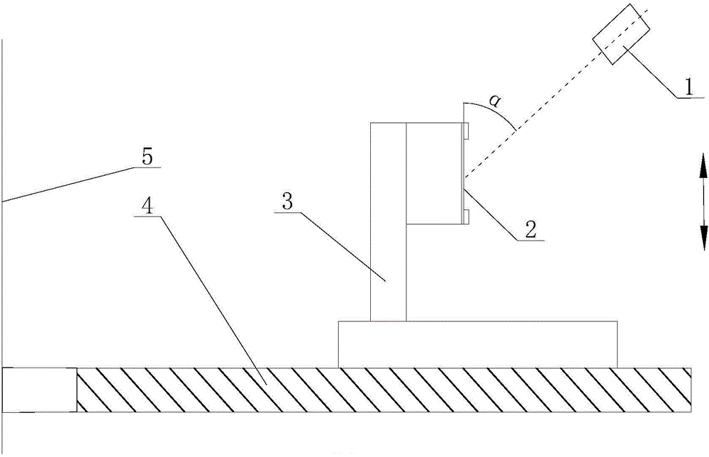
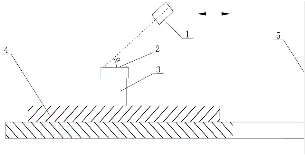
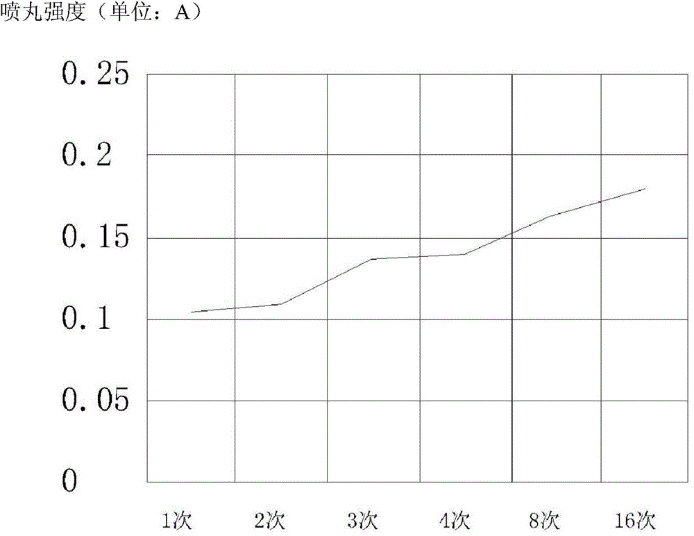
The invention discloses a move mode shot peening specimen testing method, belongs to the technical field of shot peening processing. According to the method, principles of the feeding mode for each turn, constant linear velocity and the like are introduced, so that a stable shot intensity value linear progressively increasing curve can be obtained; very important significance is provided for determining the shot parameters by technology personnel; the parameter selection success ratio is improved; also because the same linear velocity is used in the part blasting process, the quality of shots is improved greatly. The method comprises the following steps: step one, determining the motion track of a spray gun to be axial motion or radial motion according to the structure of a part, executing the step two if the motion trail is axial motion, and executing the step three if the motion track is radial motion; step two, carrying out the shot peening specimen testing method if the motion track of the spray gun is axial motion; and step three, carrying out the shot peening specimen testing method if the motion track of the spray gun is radial motion.
Description
technical field [0001] The invention belongs to the technical field of shot peening processing, and in particular relates to a test method for a moving mode shot peening test piece. Background technique [0002] The technical indicators of the parts after shot peening are not easy to be directly measured by the instrument without destroying the body. Usually, the shot peening parameters need to be determined through the test piece test. The existing shot peening test method is relatively simple and rough. For some specific parts There is a certain error in the simulation, which cannot accurately reflect the real shot peening effect. From the perspective of the gun movement mode, the feed per minute mode is mostly used at present, but in actual processing, it will be affected by the moving speed of the nozzle and the parts. The mismatch of the rotation speed causes the shot peening traces to rise in a spiral shape. It is necessary to spray the parts multiple times to obtain a...
Claims
Login to View More Application Information
Patent Timeline
 IPC IPC(8): G01N33/00G05B19/19
Inventor孟震威时旭李萌萌杨清刘中华
OwnerSHENYANG LIMING AERO-ENGINE GROUP CORPORATION