3d display device

A display device and 3D technology, applied in optics, lenses, instruments, etc., can solve problems such as narrow 3D viewing angles and affect 3D effects, and achieve the effect of improving crosstalk

Active Publication Date: 2017-01-18
TCL CHINA STAR OPTOELECTRONICS TECH CO LTD
View PDF7 Cites 0 Cited by
  • Summary
  • Abstract
  • Description
  • Claims
  • Application Information

AI Technical Summary

Problems solved by technology

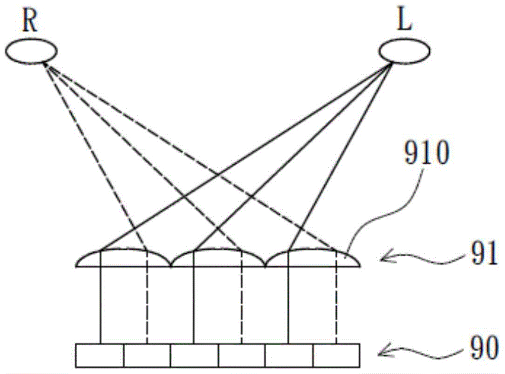
Due to the existence of lens aberration, when viewed under an improper viewing angle (for example, the viewing angle is too large), the human eye will see the image information of pixels that should not be seen, which constitutes crosstalk and affects the 3D effect
Therefore, this design makes the 3D viewing angle narrow

Method used


Image

  • 3d display device
  • 3d display device
  • 3d display device

Examples


Embodiment Construction

[0030] In order to make the above objects, features and advantages of the present invention more comprehensible, preferred embodiments of the present invention are exemplified below and described in detail in conjunction with the accompanying drawings. Furthermore, the directional terms mentioned in the present invention, such as "up", "down", "front", "back", "left", "right", "inside", "outside", "side", etc., It is only for orientation with reference to the attached drawings. Therefore, the directional terms used are used to illustrate and understand the present invention, but not to limit the present invention.

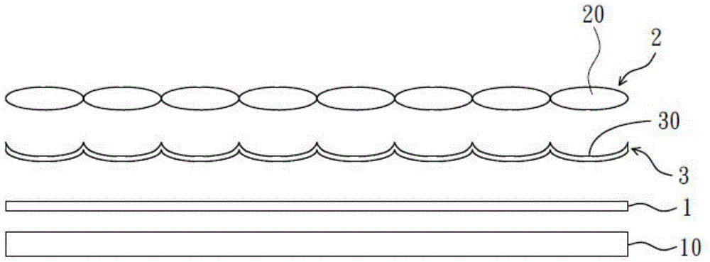
[0031] Please refer to image 3 as shown, image 3 It is a structural schematic diagram of a preferred embodiment of the 3D display device of the present invention. The 3D display device of the present invention mainly includes a display panel 1 , a collimated backlight module 10 , a lens array 2 and a curved diffuser array 3 . The display panel 1 is used to pr...


PUM


Abstract

A 3D display device includes a display panel, a collimated backlight module, a lens array and a curved diffuser array. The lens array is arranged on the surface of the display panel. The curved diffuser array is disposed between the display panel and the lens array, and the two-dimensional image of the display panel is first diffused by the curved diffuser array, and then restored to a 3D scene by the lens array. The arrangement of the lens array, the curved diffuser array and the collimation backlight module can effectively improve the crosstalk phenomenon caused by the aberration of the lens array.

Description

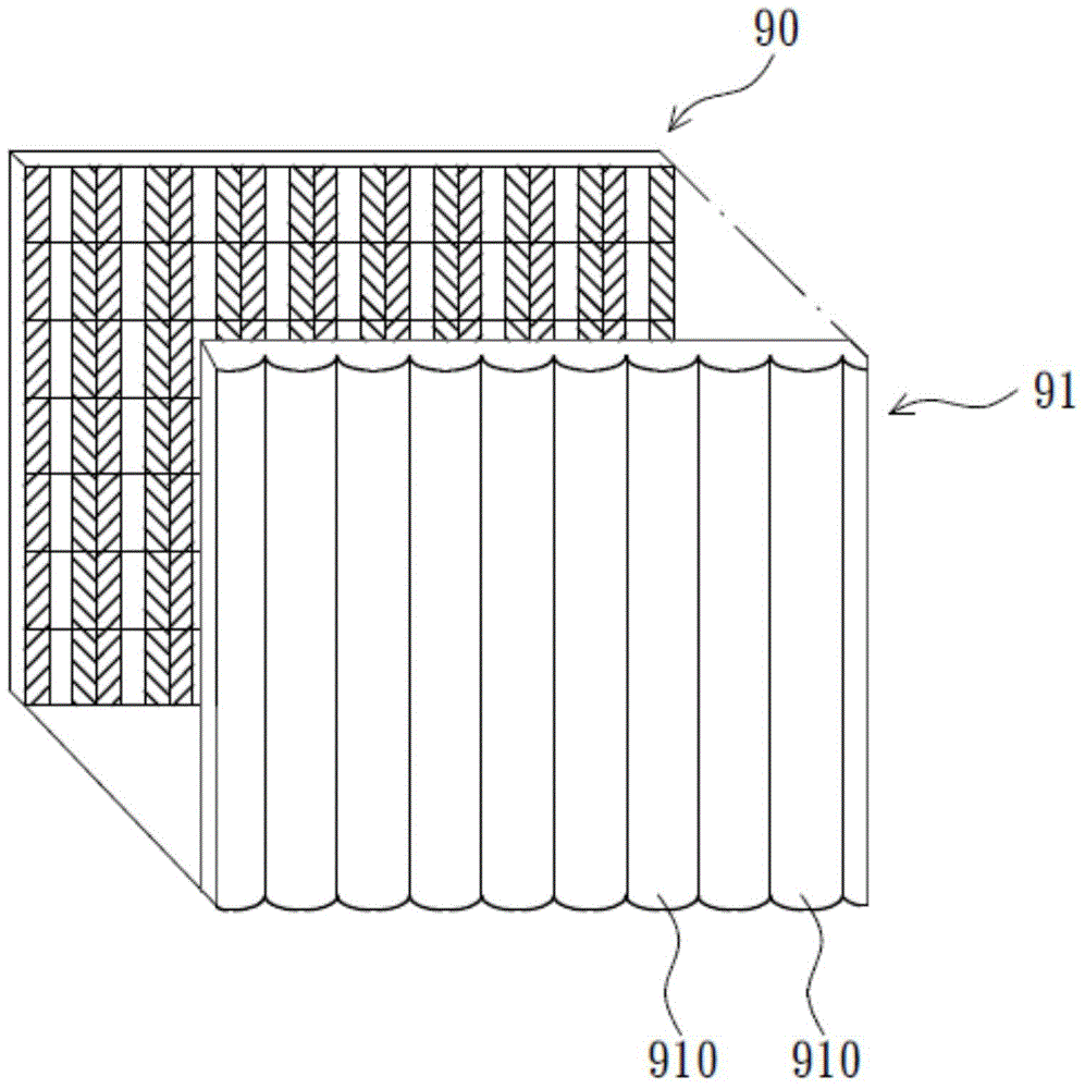
[0001] 【Technical field】 [0002] The present invention relates to a liquid crystal display technology, in particular to a 3D display device capable of improving the crosstalk problem during 3D display. [0003] 【Background technique】 [0004] In order to satisfy the visual experience, the display technology has been developed to 3D display. Existing 3D display technologies can be roughly divided into glasses-type 3D display technologies (stereoscopic display) and naked-eye 3D display technologies (auto-stereoscopic display), wherein the advantage of the naked-eye 3D display technology is the convenience of not needing additional glasses. Currently, naked-eye 3D display technology can be realized by using a parallax barrier, a lenticular lens, or a directional backlight. [0005] Please refer to figure 1 and figure 2 as shown, figure 1 It is a structural schematic diagram of an existing lenticular lens 3D display device, figure 2 It is a schematic diagram of the operatio...

Claims


Application Information

Patent Timeline
Patent Type & Authority Patents(China)
IPC IPC(8): G02B27/22G02B30/27
CPCG02B3/0012G02B5/02G02F1/133526G02F1/133504G02B30/27
Inventor 陈剑鸿
Owner TCL CHINA STAR OPTOELECTRONICS TECH CO LTD
Why Eureka
Try Eureka