Connector plug and manufacturing and assembling method thereof

A connector plug and assembly method technology, which is applied to the assembly/disassembly and connection of components and contacts of the connection device, and can solve the problems of unstable signal transmission, unstable assembly structure of the insulating seat, and mutual interference of signals, etc. problems, to achieve good contact conduction, easy molding and manufacturing, and stable signal transmission

Active Publication Date: 2015-03-25
SHENZHEN LITKCONN TECH
View PDF12 Cites 8 Cited by
  • Summary
  • Abstract
  • Description
  • Claims
  • Application Information

AI Technical Summary

Problems solved by technology

With the development needs and trends of thin and light electronic products (for example: various ultra-thin and light tablets, mobile phones, two-in-1 (2-in-1) and other special-purpose mobile devices, etc.), the design requirements for connectors are also increasing. It is becoming more and more light and thin to meet the corresponding size requirements of electronic products. The size of the connector becomes smaller, and the size of its corresponding structural components is also limited, and the distance between the upper and lower rows of contact terminals is also smaller. At this time, a new problem arises: the signals between the upper and lower rows of contact terminals will interfere with each other, and the traditional shielding structure design cannot achieve a good shielding effect, resulting in unstable signal transmission; and, the upper and lower row The assembly structure of the row of contact terminals in the insulating seat also has defects such as instability or troublesome process

Method used


Image

  • Connector plug and manufacturing and assembling method thereof
  • Connector plug and manufacturing and assembling method thereof
  • Connector plug and manufacturing and assembling method thereof

Examples


Embodiment Construction

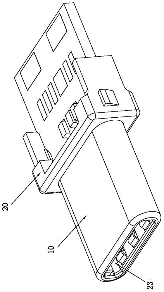
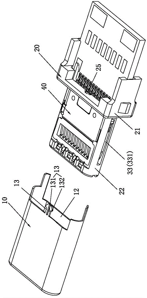
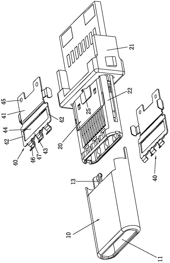
[0058] Please refer to Figure 1 to Figure 9 As shown, it shows the specific structure of the preferred embodiment of the present invention. The connector plug includes a shielding shell 10 , an insulating seat body 20 , a terminal module 30 and two baffles 40 .

[0059] Such as Figure 2 to Figure 5 As shown, the insulating seat body 20 includes a base 21 and a tongue 22 connected to the front end of the base 21. The front end of the tongue 22 is concavely provided with a slot 23 passing through the rear end of the base 21. The tongue 22 A plurality of through holes 221 penetrating through the slot 23 are opened on the upper and lower surfaces of the upper and lower surfaces respectively, and spacer arms 222 are formed between adjacent through holes 221, and the through holes 221 are provided one by one corresponding to each terminal.

[0060] Such as Figure 4 and Figure 5 As shown, the terminal module 30 includes an upper terminal module 31, a lower terminal module 32 a...


PUM


Abstract

The invention discloses a connector plug and a manufacturing and assembling method of the connector plug. The connector plug comprises a shielding shell, an insulated base, a terminal module and two baffles. The insulated base comprises a base body and a tongue plate connected to the front end of the base body. An insertion groove is formed in the front end face of the tongue plate in a backwards-concave mode and is throughout the rear end of the base body. The terminal module comprises an upper terminal module, a lower terminal module and a hook plate clamped between the upper terminal module and the lower terminal module. Positioning holes are formed correspondingly in an upper terminal port, a lower terminal port and a partitioning plate and communicated with one another. The upper terminal module, the lower terminal module and the hook plate form the integrated terminal module structure through the positioning holes in a secondary embedding mode, the terminal module is embedded into the insertion groove in the insulated base, the two baffles are arranged on the upper surface and the lower surface of the tongue plate respectively, the tongue plate and the two baffles are wrapped in the shielding shell, and the two baffles are connected with the shielding shell. In this way, the connector plug is easy to form and manufacture, fast, convenient and stable to assemble and good in shielding effect, improves the contact performance of a terminal and ensures stable signal transmission.

Description

technical field [0001] The invention relates to the technology in the field of electrical connectors, in particular to a connector plug and a manufacturing and assembling method thereof. Background technique [0002] At present, connectors are widely used in electronic products for functions such as data transmission, charging and image transmission. With the development needs and trends of thin and light electronic products (for example: various ultra-thin and light tablets, mobile phones, two-in-1 (2-in-1) and other special-purpose mobile devices, etc.), the design requirements for connectors are also increasing. It is becoming more and more light and thin to meet the corresponding size requirements of electronic products. The size of the connector becomes smaller, and the size of its corresponding structural components is also limited, and the distance between the upper and lower rows of contact terminals is also smaller. At this time, a new problem arises: the signals b...

Claims


Application Information

Patent Timeline
Patent Type & Authority Applications(China)
IPC IPC(8): H01R13/516H01R43/20
CPCH01R13/516H01R43/20
Inventor 邓辉伦
Owner SHENZHEN LITKCONN TECH
Why Eureka
Try Eureka