Motor, motor rotor and motor rotor manufacturing method

A technology of a motor rotor and a manufacturing method, which is applied in the manufacture of motor generators, stator/rotor bodies, and electric components, etc., can solve the problems of permanent magnet flanging, permanent magnet damage, and inability to be identified by instruments.

Active Publication Date: 2015-03-25
CSR ZHUZHOU ELECTRIC CO LTD
View PDF6 Cites 3 Cited by
  • Summary
  • Abstract
  • Description
  • Claims
  • Application Information

AI Technical Summary

Problems solved by technology

The permanent magnets installed in each permanent magnet slot of the permanent magnet motor have the same magnetic properties, and any two permanent magnets are repulsive, but when the first permanent magnet is installed, the magnetic steel will be quickly attracted to the front pressure plate, and the permanent magnet may Damage, but whether the permanent magnet is partially damaged cannot be identified by the instrument. In addition, when the last layer of permanent magnet is installed, due to the repulsive force, the permanent magnet will turn over or jump out

Method used


Image

  • Motor, motor rotor and motor rotor manufacturing method
  • Motor, motor rotor and motor rotor manufacturing method
  • Motor, motor rotor and motor rotor manufacturing method

Examples


Embodiment Construction

[0027] The invention provides a motor rotor and a manufacturing method of the motor rotor, which can ensure that the permanent magnet is intact and smoothly installed in place during the manufacturing process of the permanent magnet motor. In addition, the present invention also provides a motor comprising the above-mentioned motor rotor.

[0028] The technical solutions in the embodiments of the present invention will be clearly and completely described below in conjunction with the accompanying drawings in the embodiments of the present invention. Obviously, the described embodiments are only some, not all, embodiments of the present invention. Based on the embodiments of the present invention, all other embodiments obtained by persons of ordinary skill in the art without making creative efforts fall within the protection scope of the present invention.

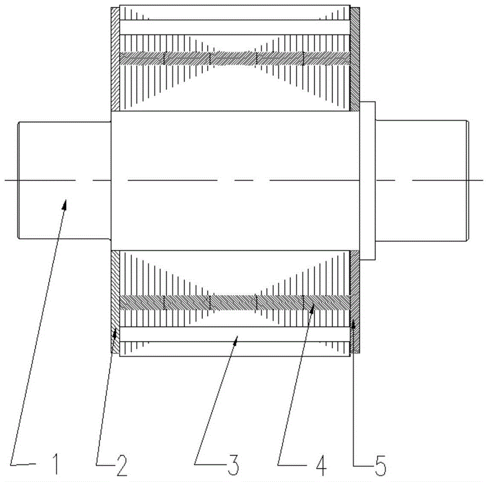
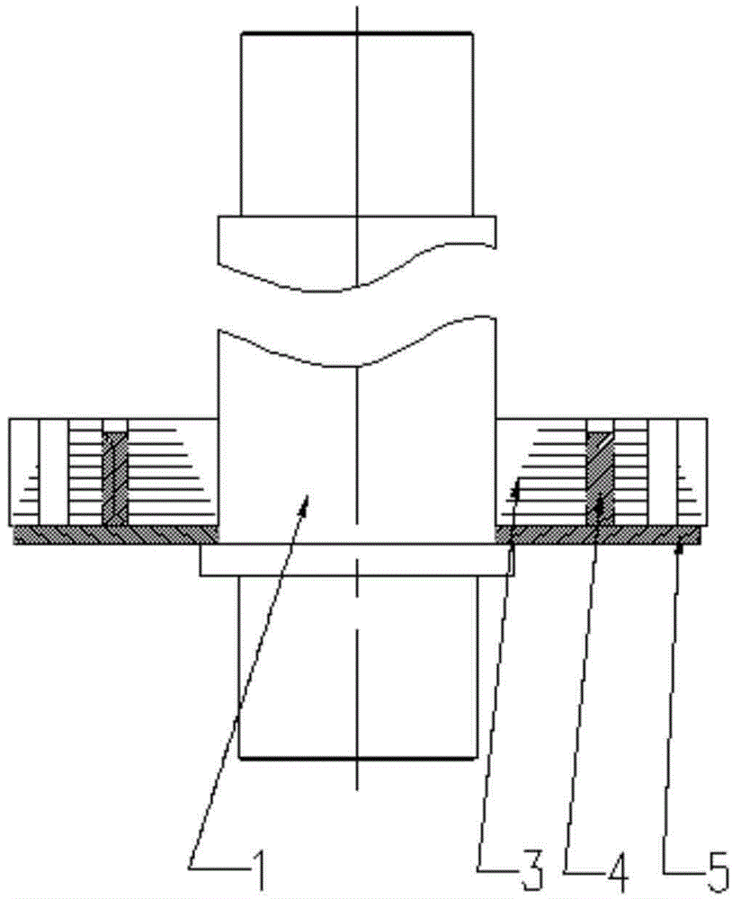
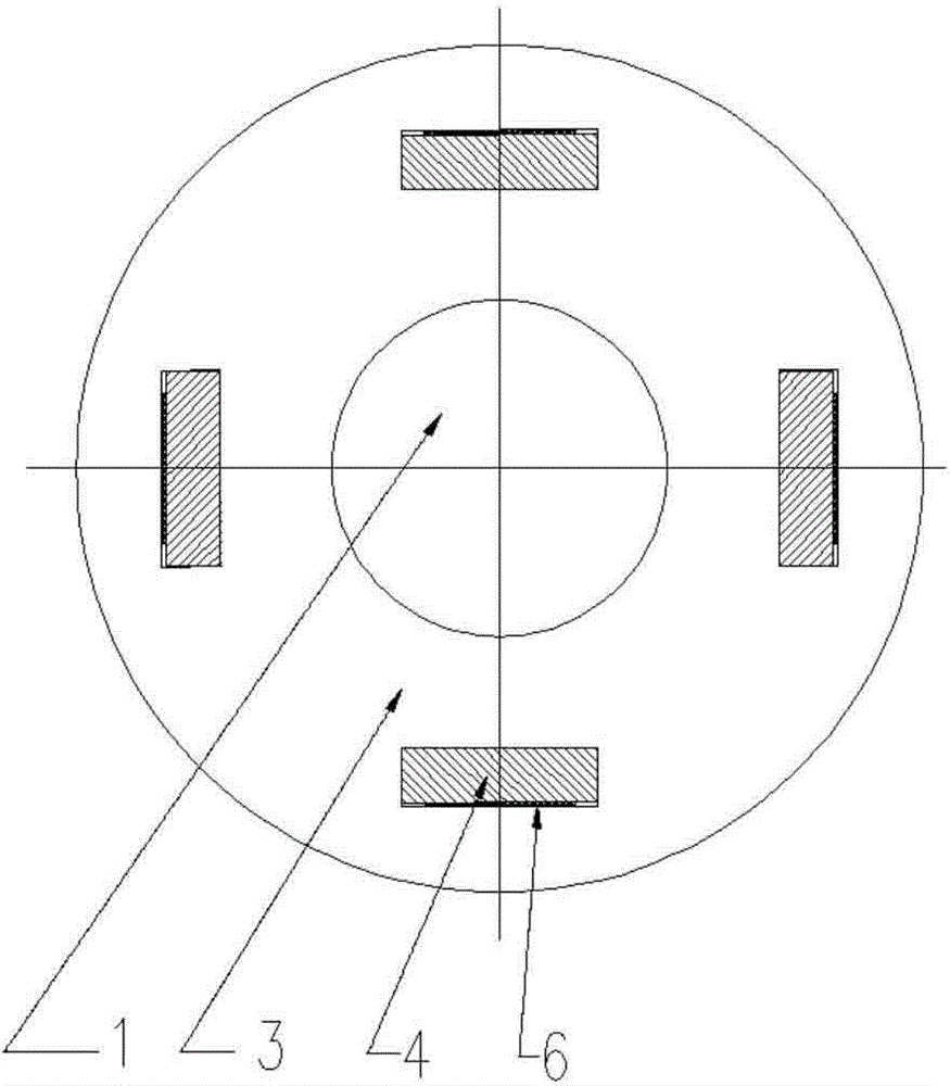
[0029] Such as Figure 1-Figure 4 as shown, figure 1 A schematic diagram of the front view structure of the motor rotor...


PUM


Abstract

The invention provides a motor rotor. The motor rotor comprises a rotary shaft and rotor cores matched with the rotary shaft in a sleeving mode, wherein the multiple rotor cores are arranged on the rotary shaft in a layered and sleeving mode in the axial direction of the rotary shaft, a permanent magnet is installed on each layer of rotor cores in the circumferential direction of the rotary shaft and is located in permanent magnet grooves of the rotor cores, and the rotary shaft is sleeved with a front pressing plate and a rear pressing plate which are arranged at the two axial ends of the rotor cores to fix the rotor cores. The rotor cores are arranged in the layered mode, the permanent magnet on each layer can be installed in place and can be controlled easily, and smooth and damage-free installation of the permanent magnets is guaranteed. The invention further provides a motor rotor manufacturing method and a motor comprising the motor rotor.

Description

technical field [0001] The invention relates to the technical field of electric motors, and more specifically, relates to a motor rotor and a manufacturing method of the motor rotor. In addition, the present invention also relates to an electric machine comprising the above-mentioned electric machine rotor. Background technique [0002] Permanent magnet motors are the direction of motor development in the future. At present, permanent magnet motors have gradually been involved in aerospace, rail transit, precision measurement and other fields. [0003] The permanent magnets in permanent magnet motors are usually formed by sintering. Such permanent magnets are relatively brittle and cannot withstand large impact forces. In high-speed permanent magnet motors, higher requirements are put forward for permanent magnets, not only requiring high heat-resistant temperature of permanent magnets, but also requiring the volume damage rate of permanent magnets to be less than 1% during...

Claims


Application Information

Patent Timeline
IPC IPC(8): H02K1/27H02K15/03
CPCH02K1/2713H02K15/03
Inventor 段宗玉杨振中姚秋华贺北平肖时峰
Owner CSR ZHUZHOU ELECTRIC CO LTD
Why Eureka
Try Eureka