
Clock pulse system, clock pulse integrated circuit and clock pulse generation method

A clock pulse and integrated circuit technology, which is applied in the fields of clock pulse system, clock pulse integrated circuit and clock pulse generation, and can solve the problems of significant sum and inability to reduce simultaneously.

Active Publication Date: 2017-05-03
VIA TECH INC
View PDF3 Cites 0 Cited by
  • Summary
  • Abstract
  • Description
  • Claims
  • Application Information

AI Technical Summary

Problems solved by technology

Therefore, the designer of the phase-locked loop has to compromise between the bandwidth and the inability to reduce both kinds of jitter at the same time
Although input jitter as well as internal jitter may be reduced to some extent in frequency adjustment, the sum of the two jitters is still significant

Method used


Image

  • Clock pulse system, clock pulse integrated circuit and clock pulse generation method
  • Clock pulse system, clock pulse integrated circuit and clock pulse generation method
  • Clock pulse system, clock pulse integrated circuit and clock pulse generation method

Examples


Embodiment Construction

[0115] The following description enables those skilled in the art to use the teachings provided by the present invention to specific applications and fulfill their needs. However, various changes to the embodiments of the present invention will be apparent to those skilled in the art, and the general principles defined herein can be applied to other embodiments. Thus, the invention is not intended to be limited to the particular embodiments described herein but is to be accorded the widest scope consistent with the principles and novel features disclosed herein.

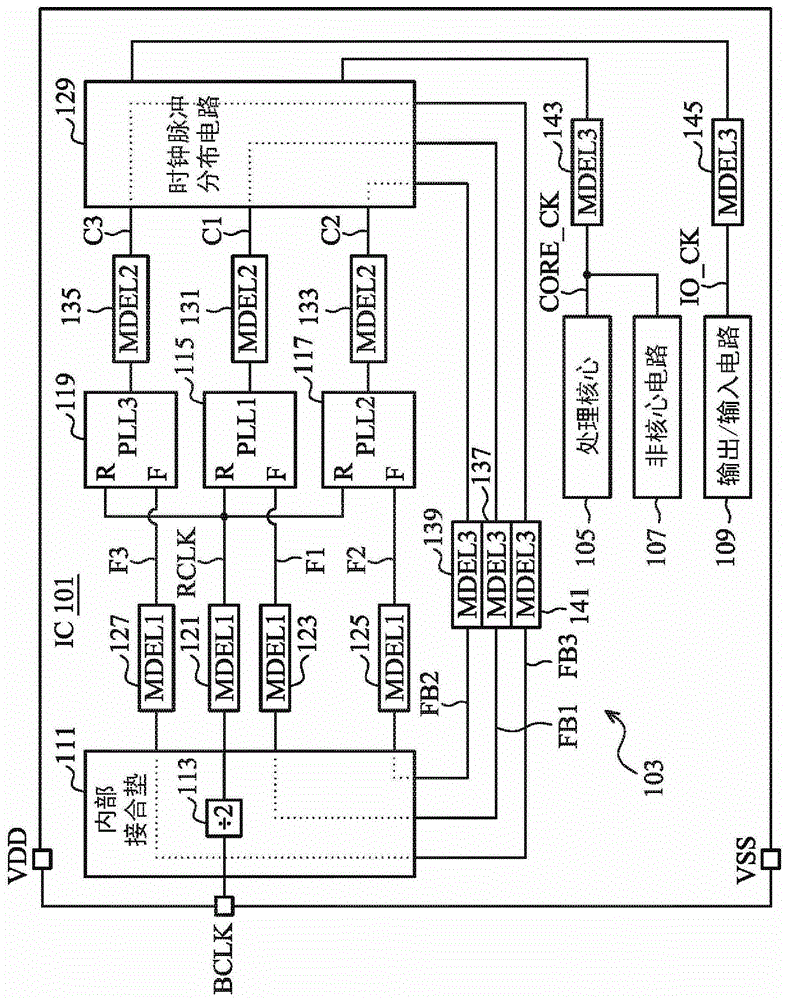
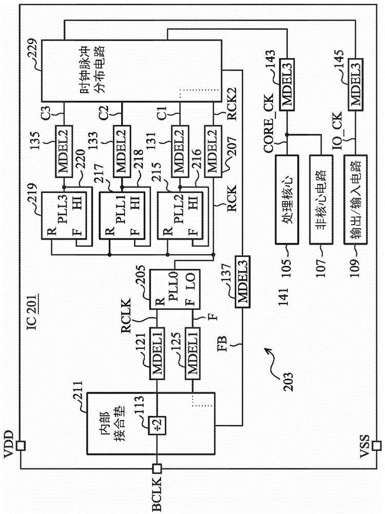
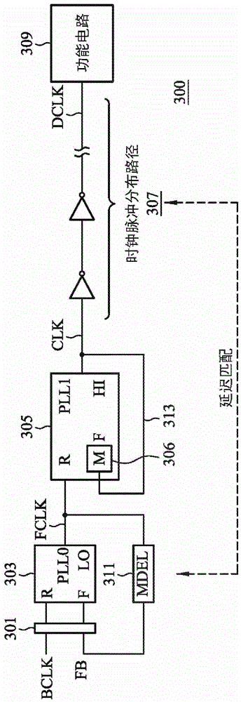
[0116]The inventors of the present case recognized the drawbacks of the conventional high-band phase-locked loops for clock pulse generation, and thus disclosed a clock system and method that utilizes a low-band phase-locked loop with a single matched clock delay path and at least one high-frequency phase-locked loop. A band PLL is used to filter out most of the clock pulse jitter. Each high-band phase-locked loop u...


PUM


Abstract

The clock pulse system, the clock pulse integrated circuit and the clock pulse generation method receive the reference clock signal through the alignment position to generate the functional clock pulse, and the functional clock pulse is provided to the functional circuit through the clock pulse path. The clock system includes a low-band PLL, a high-band PLL, and a delay path. The low frequency band PLL receives the reference clock signal and the feedback clock to provide the filtered clock. The high-band phase-locked loop receives the filter clock pulse and provides the functional clock pulse. The high-band phase-locked loop has a feedback input end coupled to the output end of the high-band phase-locked loop via a local feedback path. The delay path is coupled between the output end of the low-band PLL and the alignment position to provide a feedback clock pulse to the low-band PLL. The delay path substantially matches the clock path. The bandwidths of the low-band PLL and the high-band PLL are used to reduce input jitter and internal jitter, respectively.

Description

technical field [0001] The present invention relates to a clock pulse signal generation method and device, in particular to using a low-band phase-locked loop with a matching clock delay path to generate a low-jitter clock signal, and using at least one high-frequency phase-locked loop with a local feedback path loop to reduce jitter. Background technique [0002] Traditional clock pulse generation systems usually include at least one phase-locked loop, which is used to multiply the frequency of the reference clock pulse signal to generate one or more high-frequency clock pulse signals, which are used for synchronization or timing purposes and provided to integrated Functional circuits of circuits, semiconductor chips or similar devices. Each clock signal generated by the phase-locked loop is sent back to the feedback input end of the phase-locked loop for synchronizing the phase and frequency of the fed-back clock signal with the reference signal. Although the reference s...

Claims


Application Information

Patent Timeline
Patent Type & Authority Patents(China)
IPC IPC(8): H03K5/135H03K5/14H03L7/08
CPCH03L7/22
Inventor 达鲁斯·D·嘉斯金斯詹姆斯·R·隆柏格
Owner VIA TECH INC
Learn More