
Automatic shooting method and system of wearable device

A wearable device, automatic camera technology, applied in the parts of TV systems, image analysis, image communication, etc., can solve the problem of not being able to record images automatically and efficiently

Active Publication Date: 2015-03-25
GUANGDONG OPPO MOBILE TELECOMM CORP LTD
View PDF5 Cites 23 Cited by
  • Summary
  • Abstract
  • Description
  • Claims
  • Application Information

AI Technical Summary

Problems solved by technology

However, current wearable devices, especially smart glasses, although there are many ways to automatically take pictures and record them, such as timing pictures, blinking pictures, etc., none of them can truly and efficiently automatically record the images seen by human eyes.

Method used


Image

  • Automatic shooting method and system of wearable device
  • Automatic shooting method and system of wearable device
  • Automatic shooting method and system of wearable device

Examples


Embodiment 1

[0021] Such as figure 1 As shown, the automatic camera system of smart glasses in the first embodiment includes an eye movement detection module 1 , a calculation module 2 , a camera module 3 and a storage module 4 . Among them, the eye movement detection module 1 can be set on the frame of the smart glasses to detect the user's eye movement in real time, such as the center of the pupil as the moving point, the corner of the eye as the reference point, and the relative position between the center of the pupil and the corner of the eye as the eye movement A side reaction of the eyeball movement data, which includes the above-mentioned relative position of the pupil center and the corner of the eye, eyeball rotation angle, etc. Calculation module 2 recognizes eye pauses by analyzing eye movement data, because when people use their eyes to look at an object, the eyeballs first rotate, then pause, keep the eyeballs still, and then focus to see the image clearly Therefore, the cal...

Embodiment 2

[0028] Such as figure 2 As shown, the automatic camera system of the wearable device in the second embodiment includes an eye movement detection module 1 , a computing module 2 , a camera module 3 , a storage module 4 , a marking module 5 and a timing module 6 . Among them, the eye movement detection module 1 detects the user's eye movement in real time, and outputs eye movement data, including the angle and orientation of the eye movement. The calculating module 2 recognizes eye pauses by analyzing the eye movement data, and calculates the line of sight direction when the eye pauses according to the eye movement data such as eye rotation angle and orientation, and sends a shooting instruction to the camera module 3 .

[0029] After the camera module 3 receives the shooting instruction sent by the calculation module 2, it focuses according to the line of sight direction when the eyeballs pause, starts to shoot after the focus is completed, and outputs the photo, which is stor...


PUM


Abstract

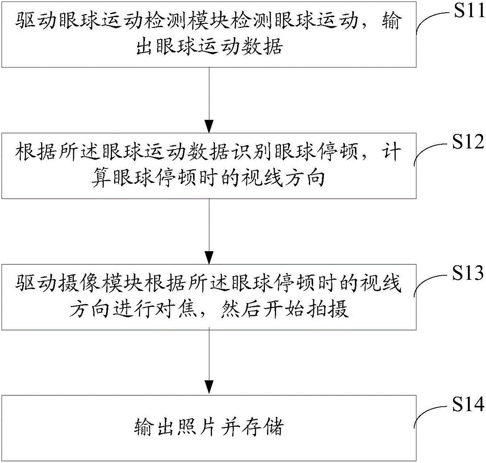
The invention discloses an automatic shooting method and system of a wearable device. The system comprises an eyeball movement detection module, a calculation module, a shooting module and a storage module. The eyeball movement detection module is used for detecting eyeball movement and outputting eyeball movement data; the calculation module is used for identifying eyeball pauses according to the eyeball movement data and outputting the line-of-sight direction formed during eyeball pausing and a shooting instruction; after receiving the shooting instruction, the shooting module conducts focusing according to the line-of-sight direction formed during eyeball pausing and then starts to shoot, and a picture is output; the storage module is used for storing the picture. When a person sees a thing with eyes, a picture can be seen clearly after the eyes are turned to fixed positions first, pause and then are focused. The method and system simulate the process, pauses in eye movement are detected, the line-of-sight direction formed during eyeball pausing is identified, automatic focusing is carried out, automatic shooting is conducted for recording, the real view field of a user can be recorded more truly and efficiently, and pictures seen by human eyes can be restored in real time.

Description

【Technical field】 [0001] The invention relates to the technical field of smart devices, in particular to an automatic camera method and system for wearable devices. 【Background technique】 [0002] With the development of science and technology, smart products have been integrated into people's daily life. Smart phones and smart tablets are relatively common smart products, which bring great convenience to people's work and life. However, the personalized needs of users are also increasing. In this case, wearable devices such as smart glasses have emerged as the times require. For example, the Google Smart Glasses released by Google in 2012. The camera has a touchpad on the frame, and the user can take pictures by blinking. However, current wearable devices, especially smart glasses, although there are many ways to automatically take pictures and record them, such as timing pictures, blinking pictures, etc., none of them can truly and efficiently automatically record the ima...

Claims


Application Information

Patent Timeline
IPC IPC(8): H04N5/232G06T7/00
Inventor 刘志超
Owner GUANGDONG OPPO MOBILE TELECOMM CORP LTD
Learn More