Control device for automatic transmission in vehicle

A technology for automatic transmissions and control devices, applied in transmissions, engine control, fluid transmissions, etc., can solve problems such as inability to absorb shocks and torque fluctuations, and achieve the effects of preventing sharp rise, simple control, and preventing speed reduction

Active Publication Date: 2015-03-25
HONDA MOTOR CO LTD
View PDF2 Cites 6 Cited by
  • Summary
  • Abstract
  • Description
  • Claims
  • Application Information

AI Technical Summary

Problems solved by technology

However, when the lock-up clutch is fully engaged, the shock and torque fluctuations transmitted between the input shaft and the output shaft cannot be absorbed.

Method used


Image

  • Control device for automatic transmission in vehicle
  • Control device for automatic transmission in vehicle
  • Control device for automatic transmission in vehicle

Examples


Embodiment Construction

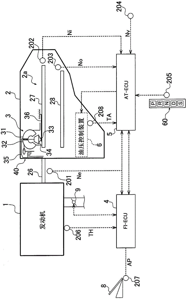
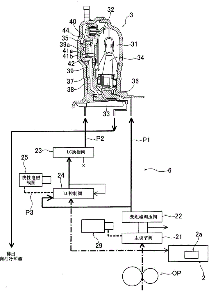
[0026] Hereinafter, embodiments of the present invention will be described in detail with reference to the drawings. figure 1 It is a schematic diagram of a drive system of a vehicle provided with a control device for an automatic transmission according to an embodiment of the present invention. also, figure 2 It is a diagram showing a torque converter 3 and a hydraulic control device (hydraulic circuit) 6 which will be described later. Such as figure 1 As shown, the vehicle of this embodiment has an engine 1 and an automatic transmission 2 coupled to the engine 1 via a fluid torque converter 3 . The automatic transmission 2 has a shifted type transmission mechanism 2 a capable of setting multiple gears (for example, 6 forward speeds / 1st reverse speed) with different gear ratios. In addition, the vehicle has: FI-ECU 4 that controls engine 1; AT-ECU (control unit) 5 that controls automatic transmission 2 including torque converter 3; rotation drive of the lock-up clutch 40...


PUM


Abstract

Sticking of a lock-up clutch (LC) is detected on the basis of the temperature (TA) of the hydraulic fluid and the slip ratio (S) of the lock-up clutch (LC). The amount of air taken into an engine is increased while LC sticking is being determined, and the increase in the amount of air taken into the engine is stopped when it has been determined that LC sticking has been released. In this way, any decrease in engine speed is effectively prevented during a period (timing) in which LC sticking occurs, and any sharp increase in engine speed (so-called sudden rotation of the engine) is effectively prevented during a period in which LC sticking does not occur (after sticking has been released). Therefore, any decrease in engine speed during lock-up clutch sticking and any sharp increase in engine speed during release of the sticking can be prevented using a relatively simple control system.

Description

technical field [0001] The present invention relates to a control device for a vehicle automatic transmission having a torque converter with a lock-up clutch. Background technique [0002] In an automatic transmission for a vehicle, as disclosed in, for example, Patent Documents 1 and 2, a lock-up clutch capable of mechanically coupling an output shaft of an engine and an input shaft of an automatic transmission is provided in a torque converter. In addition, by engaging the lock-up clutch under certain conditions, the engine rotation speed is kept low to improve fuel efficiency. [0003] Normally, the lockup clutch is engaged when the gear stage set in the automatic transmission is a predetermined gear stage. However, when the lock-up clutch is fully engaged, shocks and torque fluctuations transmitted between the input shaft and the output shaft cannot be absorbed. Therefore, slip control is performed in which the lock-up clutch is not fully engaged but is slipped accordi...

Claims


Application Information

Patent Timeline
Patent Type & Authority Applications(China)
IPC IPC(8): F02D29/00F02D9/02F02D41/04F02D45/00F16H61/14
CPCF02D9/02F16H61/14F02D29/02F02D41/022F02D41/0002F16H2059/465Y02T10/40B60W10/026B60W10/06B60W30/1884B60W30/194
Inventor 石川丰今村一彦武藤彰男
Owner HONDA MOTOR CO LTD
Why Eureka
Try Eureka