Method for operating fuel cell, and electric-power generating device

A fuel cell and operating method technology, applied to fuel cell parts, fuel cells, fuel cell additives, etc., capable of solving problems such as fuel cell power generation performance degradation

Inactive Publication Date: 2015-03-25
SHOWA DENKO KK
View PDF9 Cites 3 Cited by
  • Summary
  • Abstract
  • Description
  • Claims
  • Application Information

AI Technical Summary

Problems solved by technology

[0016] However, since a carbon-based carrier is used in the membrane electrode assembly or the fuel cell of Patent Documents 1 and 2, the presence of water degrades the carbon as the carrier as described above, and as a result, the power generation performance of the fuel cell may decrease. question

Method used

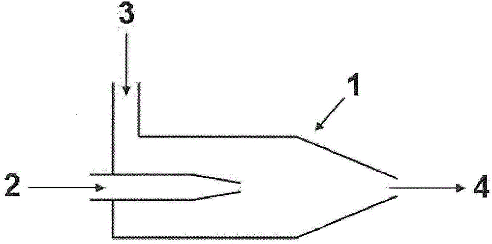

Image

  • Method for operating fuel cell, and electric-power generating device
  • Method for operating fuel cell, and electric-power generating device
  • Method for operating fuel cell, and electric-power generating device

Examples


manufacture example 1

[0214] Operation 1-1

[0215] 5 mL of titanium tetraisopropoxide and 5 mL of acetylacetone were added to a solution of 15 mL of ethanol and 5 mL of acetic acid, and stirred at room temperature to prepare a titanium-containing mixture solution. Separately, 3.76 g of glycine and 0.31 g of iron(II) acetate were added to 20 mL of pure water, and stirred at room temperature to dissolve completely, thereby preparing a glycine-containing mixture solution. Slowly add the titanium-containing mixture solution into the glycine-containing mixture solution to obtain a transparent catalyst precursor solution. Using a rotary evaporator, the temperature of the water bath was set at about 80° C., and the solvent was slowly evaporated while heating and stirring the catalyst precursor solution. The solid residue obtained by completely evaporating the solvent was pulverized finely and uniformly with a mortar to obtain a powder (1a).

[0216] This powder (1a) was placed in a tubular furnace, a...

manufacture example 2、3

[0223] Except changing the amount of distilled water, catalyzer (1), sodium carbonate, chloroplatinic acid hexahydrate and 37% formaldehyde solution as shown in table 1, carried out the operation identical with manufacture example 1, obtains platinum content as table 1 Such different composite catalysts (2), (3).

[0224] In Production Examples 4 to 22, the operations described below and in Table 2 were performed to obtain composite catalysts (4) to (22) each containing 20% ​​by mass of platinum.

manufacture example 4

[0226] Operation 4-1. Modulation of composite particles

[0227] The powder (1a) obtained in the process of operation 1-1 of Production Example 1 was prepared again.

[0228] The powder (1a) was put into a tubular furnace, and the furnace was heated at a heating rate of 10°C / min under a mixed gas atmosphere of hydrogen and nitrogen containing 4% by volume of hydrogen, which was introduced without passing through a bubbler containing distilled water. The internal temperature was raised to 900°C, and heat treatment was performed at 900°C for 1 hour. The heat-treated powder was naturally cooled to room temperature, pulverized in isopropanol with a planetary ball mill, filtered and dried to obtain powder (4b).

[0229] Operation 4-2. Hydrogen peroxide treatment

[0230] Except having changed the powder (1b) into 1.6g of powder (4b), it carried out similarly to operation 1-2 of manufacture example 1, and obtained the powder (henceforth "catalyst (4)").

[0231] Operation 4...


PUM

PropertyMeasurementUnit
specific surface areaaaaaaaaaaa

Abstract

To provide a method for operating a fuel cell by supplying a lowly humidified or non-humidified gas to an electrode, wherein the fuel cell is operated without significantly lowering the voltage compared to cases of using a highly humidified supply gas. [Solution] This method is for operating a fuel cell that comprises a membrane electrode assembly including a cathode, an anode, and an electrolyte membrane arranged between both electrodes, wherein the cathode comprises a layer that contains an oxygen reduction catalyst including composite particles that include atoms of a metal element (M1), carbon, nitrogen, and oxygen, the composite particles being particles in which primary particles of a compound of the metal element (M1) are dispersed in a structure made of carbon. In this fuel cell operation method, an oxidant gas including oxygen gas and having a relative humidity of 60% or lower at the temperature of the membrane electrode assembly is supplied to the cathode, and a fuel gas is supplied to the anode.

Description

technical field [0001] The present invention relates to a method for operating a fuel cell, and more specifically, to a method for operating a solid polymer fuel cell that supplies gas under low or no humidification. Background technique [0002] A solid polymer fuel cell (PEFC) is a fuel cell having the following form: by sandwiching a solid polymer electrolyte membrane between an anode and a cathode, fuel is supplied to the anode, and oxygen or air is supplied to the cathode, where oxygen is reduced , so as to obtain electricity. The fuel mainly uses hydrogen or methanol. Conventionally, in order to increase the reaction rate of the fuel cell and improve the energy conversion efficiency of the fuel cell, a layer containing a catalyst is provided on the surface of the cathode and / or the anode of the fuel cell. As such catalysts, precious metals such as platinum have been mainly used in the past, and development of catalysts as substitutes for noble metal catalysts has bee...

Claims


Application Information

Patent Timeline
Patent Type & Authority Applications(China)
IPC IPC(8): H01M4/90H01M4/92H01M8/02H01M8/04H01M8/10
CPCH01M4/90H01M4/9016H01M4/9083H01M4/92H01M8/02H01M8/04H01M8/04126H01M8/04835H01M8/10H01M2008/1095H01M2300/0082H01M4/8652H01M4/8663H01M4/8673H01M4/9041H01M4/921H01M4/925H01M2004/8684H01M2004/8689Y02E60/50
Inventor 手冢记庸堀北雅挥今井卓也吉村真幸伊藤祐司佐藤孝志
Owner SHOWA DENKO KK
Why Eureka
Try Eureka