Intelligent-type pneumatic actuating mechanism with fault diagnosis function

A pneumatic actuator and fault diagnosis technology, applied in the direction of engine components, mechanical equipment, valve details, etc., can solve the problems of difficulty in preparing spare parts, large number of valves, and poor pertinence, so as to ensure maintenance progress and quality, Spare parts are timely and accurate to ensure the effect of normal operation

Active Publication Date: 2014-07-02
XUZHOU AKA CONTROL VALVE CO LTD
View PDF5 Cites 15 Cited by
  • Summary
  • Abstract
  • Description
  • Claims
  • Application Information

AI Technical Summary

Problems solved by technology

Although the traditional parking maintenance scheme can completely eliminate valve failures, it has the following disadvantages: not strong pertinence, blanket inspection, long cycle, time-consuming, labor-intensive, and high cost; after the problem is found, the fault is dealt with afterwards, which affects the normal operation of the device ;The number of valves is large, and it is difficult to prepare spare parts, which affects the progress or quality of valve maintenance
Although the intelligent valve positioner with online detection function in the prior art can detect valve faults online, the valve must be matched with HART or other communication protocols, which has high cost and poor versatility; using a non-independent position sensor, such as using the online detection function, Must use intelligent valve positioner, high cost

Method used


Image

  • Intelligent-type pneumatic actuating mechanism with fault diagnosis function
  • Intelligent-type pneumatic actuating mechanism with fault diagnosis function
  • Intelligent-type pneumatic actuating mechanism with fault diagnosis function

Examples


Embodiment Construction

[0039] Below in conjunction with embodiment the present invention is further described.

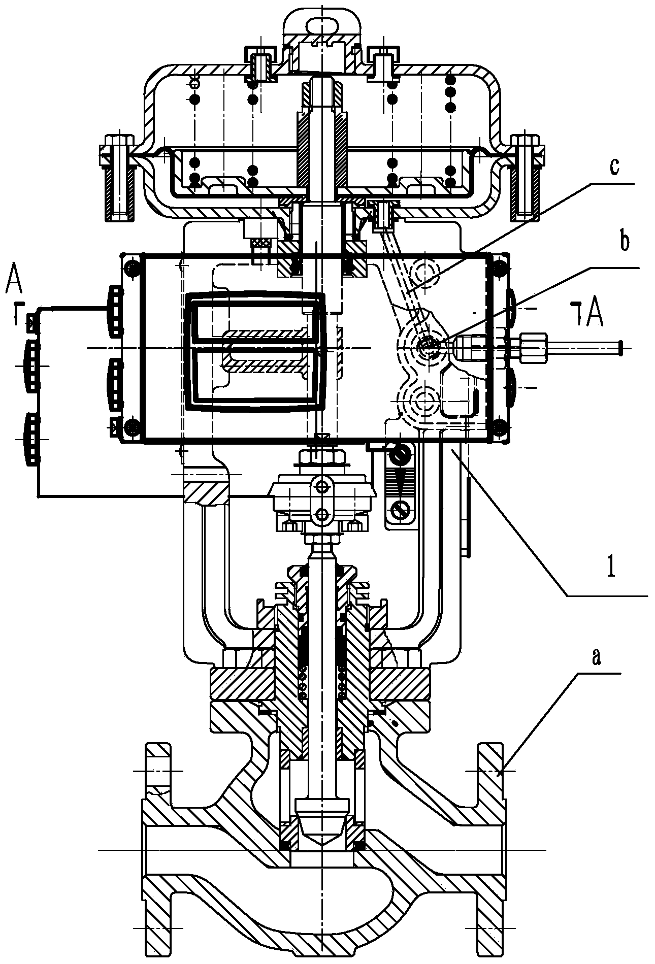
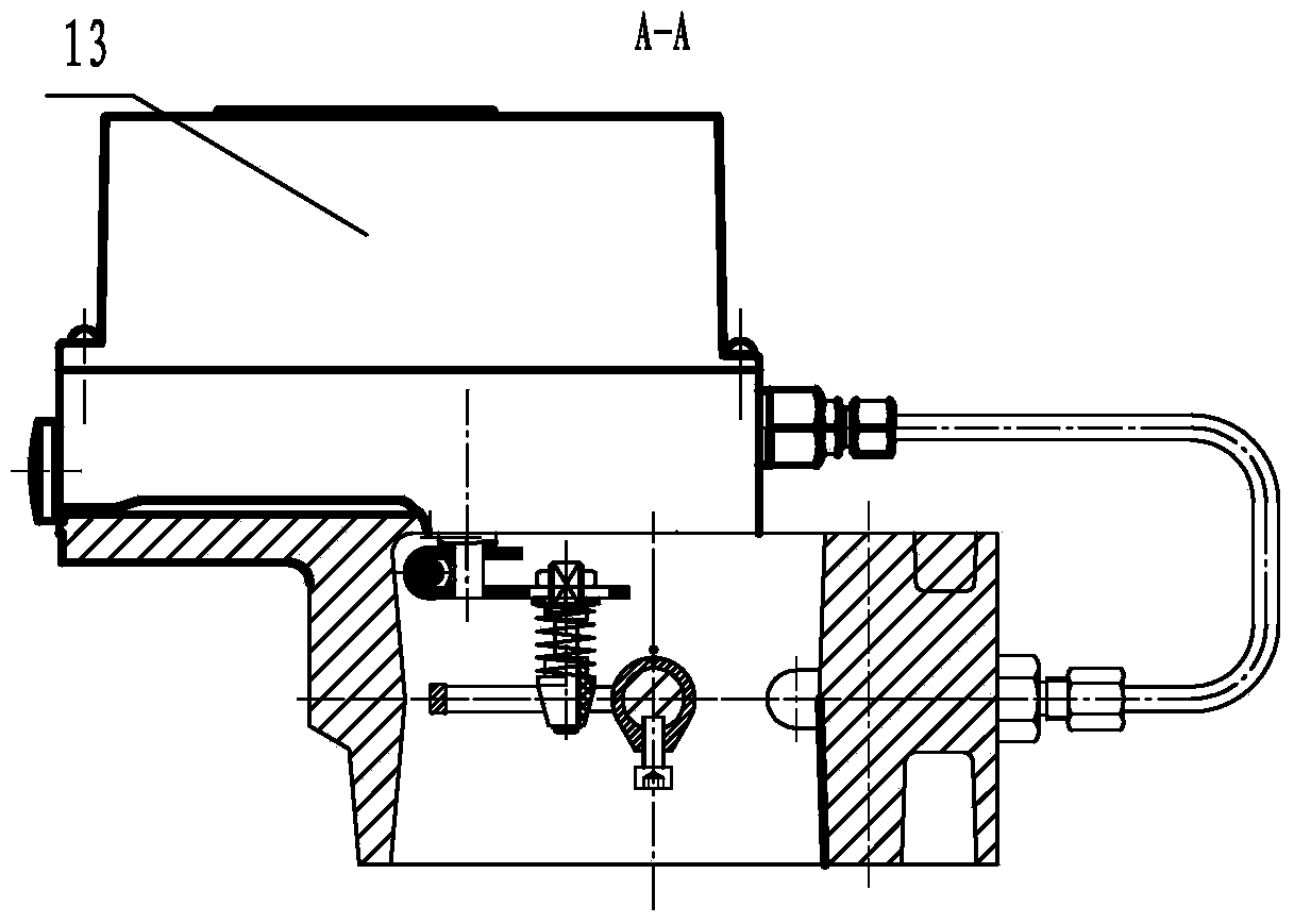
[0040] As shown in the accompanying drawings, an intelligent pneumatic actuator with fault diagnosis includes a bracket 1 connected to the regulating valve a, and a push rod 10 connected to the valve core is movably installed in the bracket 1. Above the bracket 1, there is The pressure membrane chamber, the pressure membrane chamber is mainly composed of the upper membrane cover 5 and the lower membrane cover 4. There is a diaphragm 6 between the upper membrane cover and the lower membrane cover, and the diaphragm 6 divides the pressure membrane chamber into an upper membrane chamber and the lower membrane chamber, above the diaphragm there is a tray 7 close to the diaphragm, a plurality of springs 8 are installed between the upper part of the tray 7 and the lower part of the upper membrane cover 5, and the push rod 10 The upper part of the upper part extends into the pressure membrane ch...


PUM


Abstract

The invention discloses an intelligent-type pneumatic actuating mechanism with a fault diagnosis function and belongs to the technical field of fault self-diagnosis of an adjusting valve of automated device. The intelligent-type pneumatic actuating mechanism comprises a support and a pressure film chamber, a push rod is movably mounted in the support, an air pressure signal inlet and a clamping sleeve straight-through joint are arranged on the support, the air pressure signal inlet is communicated with the pressure film chamber, a feedback component I is arranged on the push rod, a long hole I is arranged on a feedback plate I of the feedback component I, a fault detector is mounted on the support, a feedback component II and a potentiometer component are arranged in the fault detector, a roller of the feedback component II extends into the long hole I of the feedback plate I, a hollow pipe communicated with the pressure film chamber is arranged in a sealed shell of the fault detector, a pressure sensor is arranged on the hollow pipe, a shielding box component is arranged in the fault detector, a microprocessor is mounted in the shielding box component, and the pressure sensor and the potentiometer component are electrically connected with the microprocessor. The intelligent-type pneumatic actuating mechanism can realize online detection, find problems in advance and guarantee normal running of a device, so that cost is reduced.

Description

technical field [0001] The invention relates to a pneumatic actuator for a regulating valve, which belongs to the technical field of self-diagnosis of regulating valve faults of automatic devices. Background technique [0002] At present, most of the fault diagnosis in the control valve industry is realized by shutting down for maintenance. The instrument department formulates the valve maintenance plan, and the control valve on the device is shut down for maintenance on a periodic basis. Generally, the control valve on the entire device can be overhauled once every 1-3 years . Specifically: contact a professional maintenance company to sign a maintenance contract—on-site inspection of the regulating valve that needs to be repaired—make a maintenance plan—estimate and prepare spare parts—process emptying—parking—reserve time for maintenance companies to enter the maintenance site—safety education—valve Offline—arrive at the maintenance site—test the static characteristics o...

Claims


Application Information

Patent Timeline
Patent Type & Authority Applications(China)
IPC IPC(8): F16K31/126F16K37/00
CPCF16K31/1262F16K37/0025
Inventor 程路
Owner XUZHOU AKA CONTROL VALVE CO LTD
Why Eureka
Try Eureka