Substrate transfer processing apparatus

Active Publication Date: 2011-03-03
ULVAC INC
View PDF3 Cites 15 Cited by
  • Summary
  • Abstract
  • Description
  • Claims
  • Application Information

AI Technical Summary

Benefits of technology

[0018]Since the mounting table is lightweight, the mounting table can be easily handled and the facility cost and running cost of the moving device for moving the mounting table are also low. The strength of the mounting table is high as compared to a case where the thickness is simply reduced. Since the mo

Problems solved by technology

However, granite is heavy in weight, and in order to move the substrate-mounting table at a high speed, a high-power moving unit

Method used


Image

  • Substrate transfer processing apparatus
  • Substrate transfer processing apparatus
  • Substrate transfer processing apparatus

Examples


Embodiment Construction

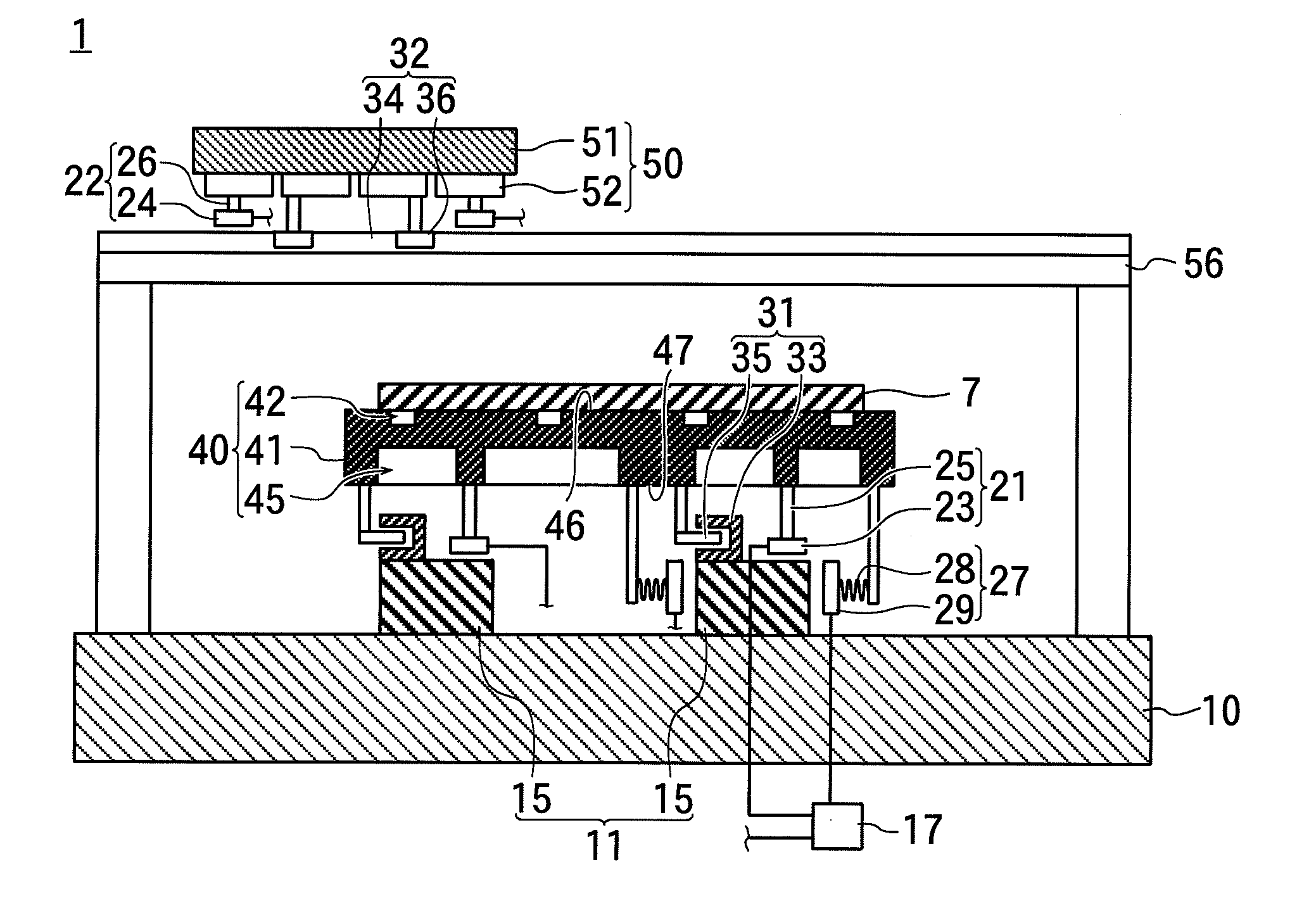
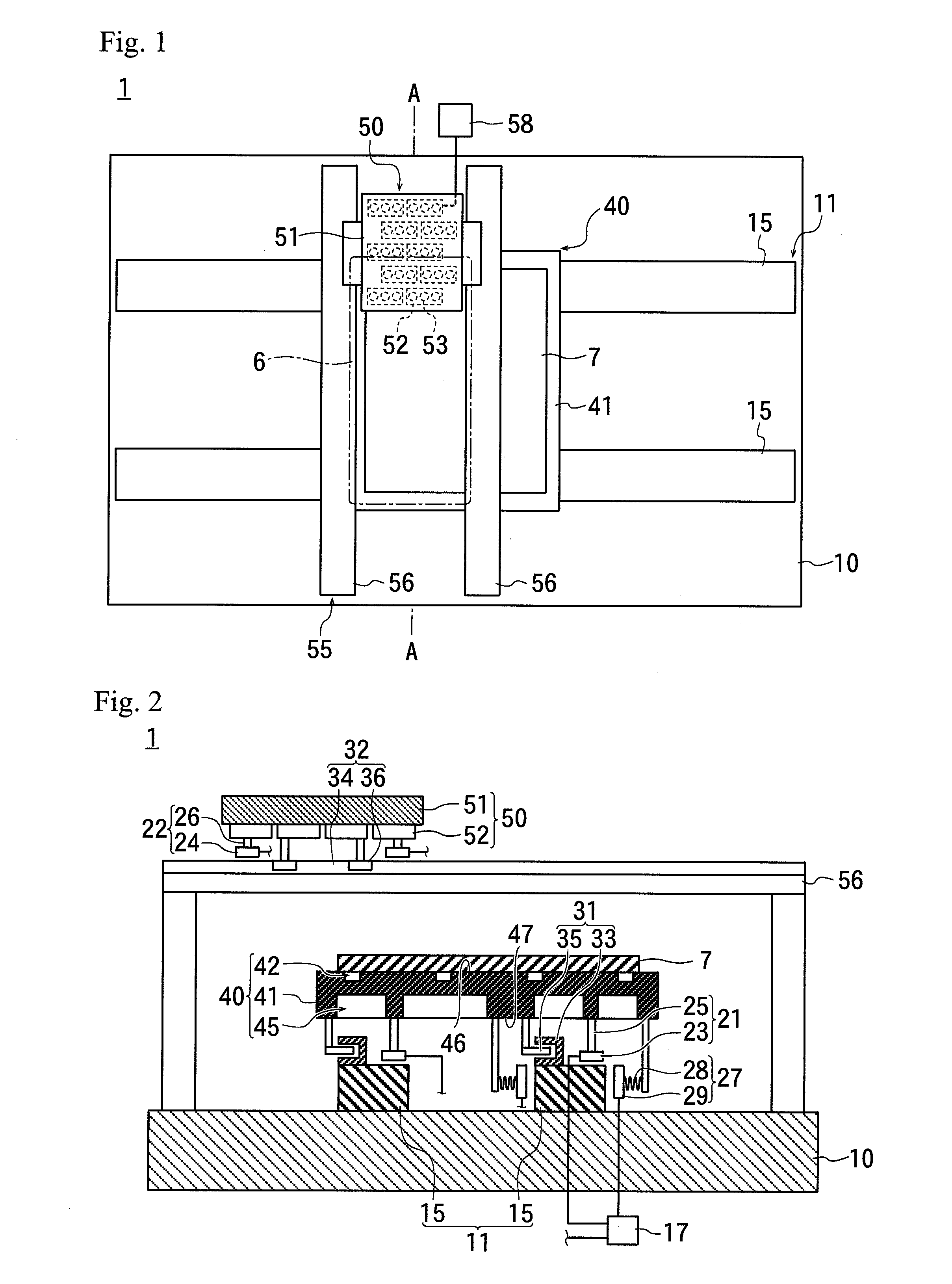
[0025]FIG. 1 is a plan view of a substrate transfer processing apparatus 1 which is an example of a processing apparatus of the present invention; and FIG. 2 is a cross-sectional view along line A-A of FIG. 1.

[0026]The substrate transfer processing apparatus 1 includes a pedestal 10, a track 11 for a substrate disposed on the pedestal 10, a travel device 21 for a substrate disposed on the track 11 for a substrate, and a mounting table 40 attached to the travel device 21 for a substrate.

[0027]Each track 11 for a substrate includes at least one rail 15.

[0028]The rail 15 of the track 11 for a substrate linearly extends on the surface of the pedestal 10. If the number of rails 15 of the track 11 for a substrate is two or more, the extension directions of the respective rails 15 are parallel to each other.

[0029]The travel device 21 for a substrate includes an air bearing 23 disposed on the rail 15 and a support shaft (support member) 25 having a lower end which is attached to the air bea...


PUM

PropertyMeasurementUnit
Speedaaaaaaaaaa
Areaaaaaaaaaaa

Abstract

A substrate transfer processing apparatus capable of processing a substrate at high speed is provided. A mounting table on which a substrate is mounted includes a plate-shaped main body and a recessed part formed in a rear surface of the plate-shaped main body. Since the mounting table is lightweight as compared to the mounting table before the recessed part is formed therein, the load on a motor is small and the running cost is low even when the mounting table is moved at high speed. Because the plate-shaped main body is made of granite, the mounting surface can be made flat and smooth by polishing. Since the mounting surface is flat and smooth, the accuracy in positioning the substrate is high.

Description

[0001]This application is a continuation of International Application No. PCT / JP2009 / 054857 filed Mar. 13, 2009, which claims priority to Japanese Patent Document No. 2008-071479, filed on Mar. 19, 2008. The entire disclosures of the prior applications are herein incorporated by reference in their entireties.BACKGROUND[0002]The present invention relates to processing apparatuses which perform a substrate processing while transferring a substrate.[0003]Conventionally, a substrate transfer apparatus (such as, a moving stage) has been used in performing a substrate processing while moving a processing unit such as a print head, and a substrate relative to each other.[0004]In such a substrate transfer apparatus, the flatness and smoothness of a mounting surface for mounting a substrate is required in order to control a positional relationship between the processing unit and the substrate with high accuracy. Conventionally, the required flatness was around 100 μm, while in recent years a...

Claims


Application Information

Patent Timeline
IPC IPC(8): B05C13/00H01L21/677B05C5/00
CPCB65G49/065B65G2249/04Y10T29/53961H01L21/67742G01N21/956
Inventor INOUE, YUYATANIFUJI, TAMOTSUTANAKA, HISATOTAKAHASHI, MAKOTOSEKINE, KUNIYOSHI
Owner ULVAC INC
Why Eureka
Try Eureka