

Machining die and method for rotor of brushless motor
A brushless motor and mold processing technology, used in forming tools, manufacturing tools, metal processing equipment, etc., can solve the problems of increased workload, low punching accuracy, easy bumping and scratching, etc., to ensure product quality and processing accuracy. , Improve production efficiency and ensure the effect of machining accuracy
- Summary
- Abstract
- Description
- Claims
- Application Information
AI Technical Summary
Problems solved by technology
Method used
Image

Examples
Embodiment
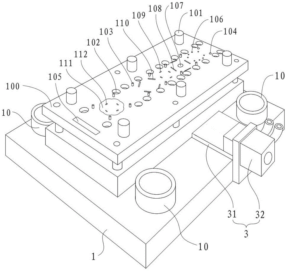
[0038] see figure 1 and figure 2 , the invention discloses a processing mold for a brushless motor rotor, comprising an upper mold base 1 and a lower mold base 2, the upper mold base 1 is provided with an upper template 100, the lower mold base 2 is provided with a lower template 200, and the upper template A processing area is formed on the 100 and the lower template 200, wherein:
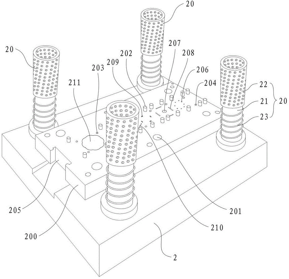
[0039] Cooperate figure 1 and figure 2 As shown, the upper mold base 1 is provided with a fixing sleeve 10 around the upper template 100, and the lower mold base 2 is provided with a fixing piece 20 matched with the fixing sleeve 10. The fixing piece 20 includes a fixing column 21 and a ball sleeve 22. And the spring 23, the fixed column 21 is fixed on the lower mold base 2, the ball sleeve 22 and the spring 23 are respectively sleeved on the fixed column 21, the spring 23 is located below the ball sleeve 22, and the fixed sleeve 10 is sleeved on the ball sleeve 22 on.
[0040] A row of pos...
PUM
 Abstract
Description
Claims
Application Information