Scaffold cross rod connector and production process thereof

A production process and scaffolding technology, applied in the connection of scaffolding, housing structure support, housing structure support and other directions, can solve problems such as affecting the orderly stacking of crossbars, achieve good economic benefits, efficient and convenient production process, and low scrap rate. Effect

Inactive Publication Date: 2015-04-01
莫彩兰
View PDF0 Cites 6 Cited by
  • Summary
  • Abstract
  • Description
  • Claims
  • Application Information

AI Technical Summary

Problems solved by technology

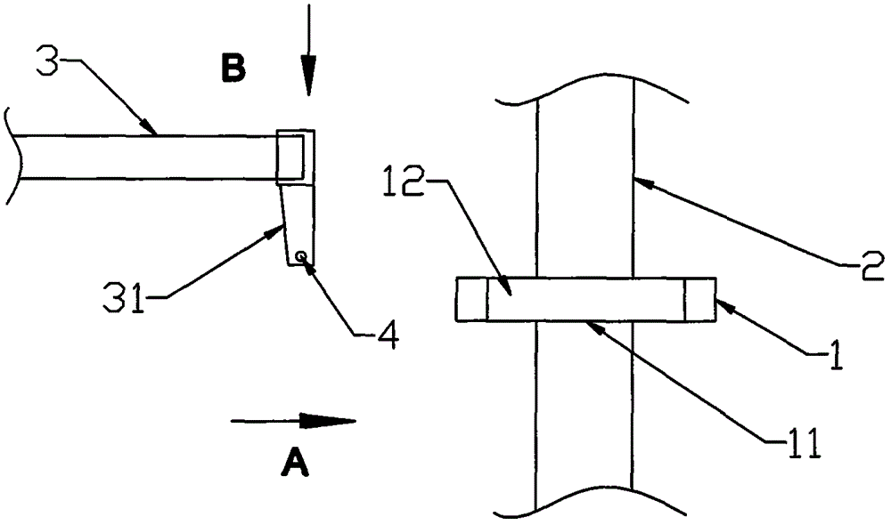
During installation, firstly, the cross bar 3 moves the joint 31 to the top of the corresponding positioning button hole 12 of the buckle plate 1 along the direction of the arrow A, and then inserts it into the positioning button hole 12 along the direction of the arrow B, that is, the horizontal bar 3 and the vertical joint are realized. Connection for rod 2; see Figure 4 , the connect

Method used


Image

  • Scaffold cross rod connector and production process thereof
  • Scaffold cross rod connector and production process thereof
  • Scaffold cross rod connector and production process thereof

Examples


Example

[0032] The first embodiment of the scaffolding crossbar joint

[0033] Such as Figure 5 As shown, the technical solution adopted by the scaffold crossbar joint of the present invention is: the scaffold crossbar joint 4 includes a plug pin 41, a positioning fixing joint 42, and the positioning fixing joint 42 and the plug pin 41 are integrally formed. The positioning fixing joint 42 includes two connecting reinforcing ribs 421 and two butterfly positioning pieces 422; the plug pin 41 is formed by two metal pieces 411 tightly attached along the Z axis. The bottoms of the two metal pieces 411 are connected as a whole. The cross-sectional width of the pin 41 is wide at the top and narrow at the bottom. The pin 41 has a positioning protrusion 412 on the surface close to one end of the connecting stiffener 421, and the lower end of the pin 41 has a positioning pin hole 414; the connecting stiffener 421 is made of a metal sheet 411 extends upward along the Z axis. Two butterfly positio...


PUM


Abstract

The invention discloses a scaffold cross rod connector which comprises a connection pin, a positioning fixing connector. The connection pin is formed by tightly adhering two metal pieces along a Z-shaft, the positioning fixing connector and the connection pin are integrally formed, and the positioning fixing connector comprises two connecting reinforcement ribs formed by the metal pieces extending along the Z-shaft upwards and further comprises two butterfly positioning pieces symmetrically distributed along the Z-shaft. The butterfly positioning pieces and the connecting reinforcement ribs are reversely bent around the Z-shaft and integrally formed, and the inscribed circles or inscribed ovals of the two butterfly positioning pieces are matched with inner holes of a cross rod. The invention further discloses a production process of the scaffold cross rod connector. The scaffold cross rod connector and the production process are suitable for scaffolds in the building industry.

Description

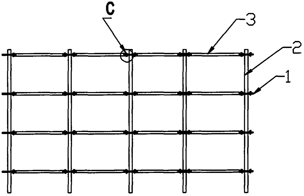
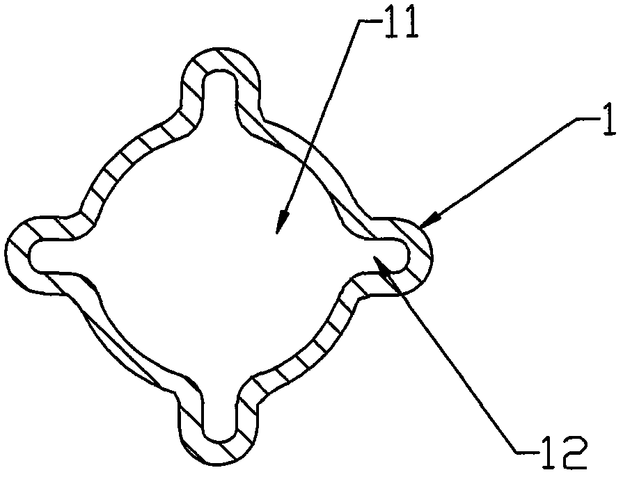
Technical field [0001] The invention relates to a scaffold crossbar joint, and also relates to a production process of the scaffold crossbar joint. Background technique [0002] In the prior art, the joint of the scaffold cross bar is welded to the end of the scaffold cross bar and then plugged into the buckle plate of the vertical pole, see figure 1 , Scaffolding includes horizontal bar 3, vertical bar 2, and vertical bar 2 with N buckle plates 1, N ≥ 1, see figure 2 , The buckle plate 1 has a central through hole 11; four positioning buckle holes 12 are symmetrically distributed around the central through hole 11 on the disc body. See image 3 , The cross bar 3 with the joint 31 can be inserted into the positioning buckle hole 12 of the buckle plate 1 through which the central through hole 11 and the vertical bar 2 are fixed to each other. During installation, first, the cross bar 3 moves the joint 31 in the direction of arrow A above the corresponding positioning button hole ...

Claims


Application Information

Patent Timeline
IPC IPC(8): E04G7/14B23P15/00B21D35/00
Inventor 莫彩兰
Owner 莫彩兰
Why Eureka
Try Eureka