Profile corner system

A technology of corners and profiles, applied in the direction of corner joints/side joints, etc., can solve problems such as increased production costs, differences, and installation obstacles, and achieve the effects of reducing the number of parts, light overall structure, and easy installation

Active Publication Date: 2016-05-18
佛山市三水和美斯金铝业有限公司
View PDF8 Cites 0 Cited by
  • Summary
  • Abstract
  • Description
  • Claims
  • Application Information

AI Technical Summary

Problems solved by technology

Although the structure is relatively strong, but too many loose parts are easy to lose, and the structure of the horizontal and vertical parts is different, which lacks versatility and increases the production cost. In addition, the small screw head can be made as a countersunk head at most, otherwise the convexity will cause the rest of the corner position. The installation obstacle of the component, and the countersunk head must thicken the thickness of the horizontal and vertical pieces, so that the overall obstacle is greater
In addition, the small screw only plays the function of "keeping the surface of the horizontal member / vertical member in close contact with the outer surface of the profile", and does not more effectively play the role of transmitting the tension force of the oblique long screw

Method used


Image

  • Profile corner system
  • Profile corner system
  • Profile corner system

Examples


Embodiment S1

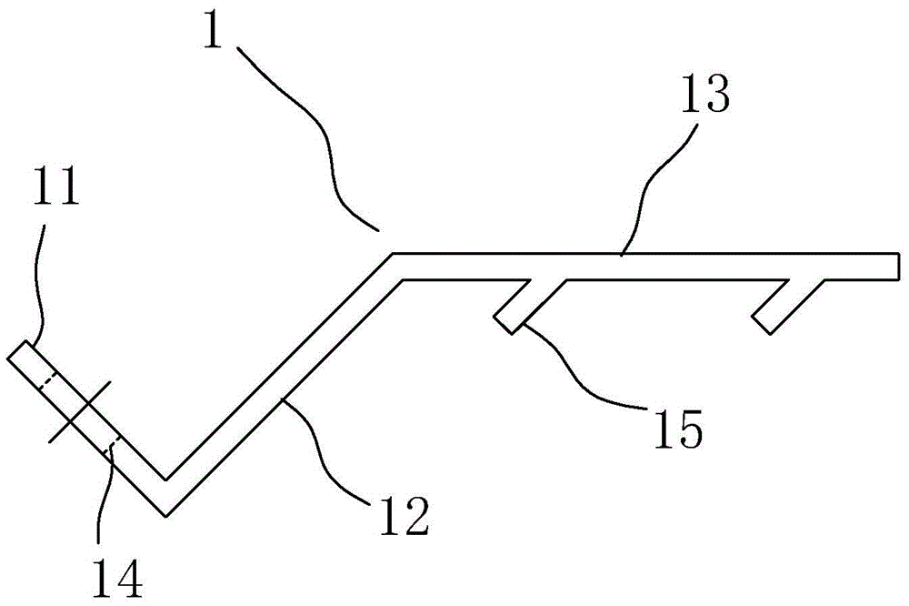
[0033] refer to figure 1 , a profile corner pull piece, comprising a pull piece main body 1, the pull piece main body 1 is in the shape of a narrow strip as a whole, and is sequentially bent from the head end to the tail end to form a connecting section 11 and a hook pull section 13, The connection section 11 has a connection hole 14 , and the hook section 13 punches out more than one pull hook 15 , and the pull hook 15 as a whole is straight or curved toward the head end of the pull piece main body 1 . In order to reduce the length of the corner cavity of the profile, sometimes a transition section 12 is provided between the connection section 11 and the hook section 13, and the connection section 11, the transition section 12, and the hook section 13 are integrated. Of course, if the position is suitable, for example, the external setting of the pull code group at the corner of the profile is required in the future, then the transition section 12 can be made very short, even...

Embodiment S2

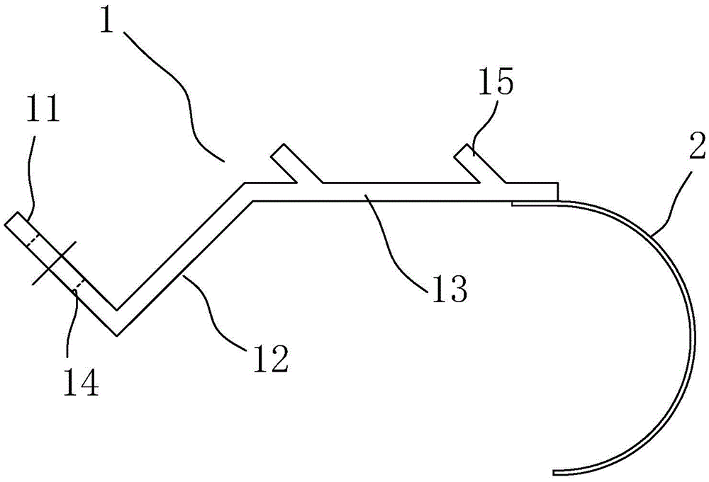
[0035] refer to figure 2 , the profile corner of embodiment S2 is basically the same as that of embodiment S1, but the rear section or tail end of hook pull section 13 is also connected with elastic abutting body 2, and the stretching direction of elastic abutting body 2 is the hook The opposite direction of the side where the drag hook 15 on the pull section 13 is located. In practice, the elastic supporting body 2 can be a shrapnel or an elastic steel wire, etc., which is mainly used to lean against the inner cavity when the pull code group is installed in the corner of the profile, so as to ensure that the connecting section is tightly attached to the inner cavity wall of the profile and is not easy to loosen. take off.

Embodiment S3

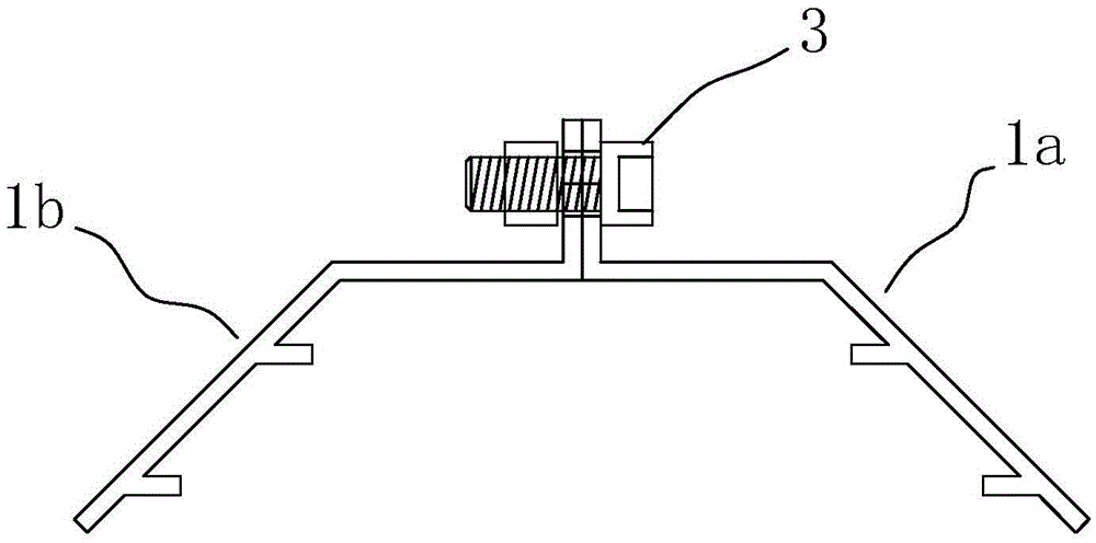
[0038] refer to image 3 , the profile corner position pull code group of embodiment S3 comprises horizontal pull code sheet 1a and vertical pull code sheet 1b, and described horizontal pull code sheet 1a is the profile corner position pull code sheet described above, is connected with horizontal pull code sheet 1a The bottom surface of the section is a mirror-image symmetrical plane, and the shape and structure of the vertical pull code sheet 1b is basically mirror-image-symmetrical to the horizontal pull code sheet 1b. A connecting screw 3 passes through the connecting hole of the horizontal pull code sheet 1a and the vertical pull code sheet 1b at the same time. The horizontal pull code sheet 1a and the vertical pull code sheet 1b are connected together.

[0039] In order to make it easier to overlap the two pull codes in practice and not easy to rotate relative to the connecting screw 3 to make installation inconvenient, further, the connecting section of the horizontal pu...


PUM


Abstract

The invention discloses a profiled corner tension fitting unit, a profiled corner tension plate and a profiled corner system employing the profiled corner tension fitting unit and the profiled corner tension plate. The profiled corner tension plate comprises a plate body which is elongated and which is bent from front to tail to provide a connecting segment and a hooking segment; the connecting segment is provided with a connecting hole; the hooking segment is provided with more than one pull hook; each pull hook is straightly extended or bent towards the front of the plate body. The profiled corner tension fitting unit comprises a transverse tension plate and a vertical tension plate which are connected together through connecting screws. The profiled corner system comprises the profiled corner tension fitting unit, a transverse frame and a vertical frame; the profiled corner tension fitting unit allows the transverse frame and the vertical frame to be connected together through the pull hooks. The profiled corner tension plate, the profiled corner tension fitting unit and the profiled corner system have the advantages that parts are few, the structure is simple, the cost is low, connection is reliable, and the profiled corner tension plate, the profiled corner tension fitting unit and the profiled corner system are widely applicable to assembly of profiled corners of doors and windows.

Description

technical field [0001] The invention relates to the field of door and window profile assembly structures, in particular to a profile corner position system in the assembly structure and assembly accessories used in the system. Background technique [0002] In the profile assembly structure of doors and windows, there will inevitably be corner positions, such as the right-angle corner positions of doors and windows, etc., which are generally made of two profiles (or combined profiles) at a certain angle, obliquely cutting off the profile ends and adding Spliced ​​by connecting accessories. If the cutting angle is 45 degrees, standard right-angle frames for doors and windows can be spliced ​​and assembled. However, since the profiles are independent of each other, how to ensure the alignment of the intersection lines of the two, the alignment of the cutting bevels, and the leveling of the profile surfaces during splicing is a big problem. [0003] CN102182386A discloses a pr...

Claims


Application Information

Patent Timeline
Patent Type & Authority Patents(China)
IPC IPC(8): E06B3/98
Inventor 朱成祥
Owner 佛山市三水和美斯金铝业有限公司
Why Eureka
Try Eureka